Viscometer
A viscometer (also called viscosimeter) is an instrument used to measure the viscosity of a fluid. For liquids with viscosities which vary with flow conditions, an instrument called a rheometer is used. Viscometers only measure under one flow condition.
In general, either the fluid remains stationary and an object moves through it, or the object is stationary and the fluid moves past it. The drag caused by relative motion of the fluid and a surface is a measure of the viscosity. The flow conditions must have a sufficiently small value of Reynolds number for there to be laminar flow.
At 20.00 degrees Celsius the dynamic viscosity (kinematic viscosity x density) of water is 1.0038 mPa·s and its kinematic viscosity (product of flow time x Factor) is 1.0022 mm2/s. These values are used for calibrating certain types of viscometers.
Standard laboratory viscometers for liquids
U-tube viscometers
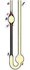
These devices are also known as glass capillary viscometers or Ostwald viscometers, named after Wilhelm Ostwald. Another version is the Ubbelohde viscometer, which consists of a U-shaped glass tube held vertically in a controlled temperature bath. In one arm of the U is a vertical section of precise narrow bore (the capillary). Above there is a bulb, with it is another bulb lower down on the other arm. In use, liquid is drawn into the upper bulb by suction, then allowed to flow down through the capillary into the lower bulb. Two marks (one above and one below the upper bulb) indicate a known volume. The time taken for the level of the liquid to pass between these marks is proportional to the kinematic viscosity. Most commercial units are provided with a conversion factor, or can be calibrated by a fluid of known properties. The time required for the test liquid to flow through a capillary of a known diameter of a certain factor between two marked points is measured. By multiplying the time taken by the factor of the viscometer, the kinematic viscosity is obtained.
Such viscometers can be classified as direct flow or reverse flow. Reverse flow viscometers have the reservoir above the markings and direct flow are those with the reservoir below the markings. Such classifications exist so that the level can be determined even when opaque or staining liquids are measured, otherwise the liquid will cover the markings and make it impossible to gauge the time the level passes the mark. This also allows the viscometer to have more than 1 set of marks to allow for an immediate timing of the time it takes to reach the 3rd mark, therefore yielding 2 timings and allowing for subsequent calculation of Determinability to ensure accurate results. The use of two timings in one viscometer in a single run is only possible if the sample being measured has Newtonian properties. Otherwise the change in driving head which in turn changes the shear rate will produce a different viscosity for the two bulbs.
Falling sphere viscometers

Stokes' law is the basis of the falling sphere viscometer, in which the fluid is stationary in a vertical glass tube. A sphere of known size and density is allowed to descend through the liquid. If correctly selected, it reaches terminal velocity, which can be measured by the time it takes to pass two marks on the tube. Electronic sensing can be used for opaque fluids. Knowing the terminal velocity, the size and density of the sphere, and the density of the liquid, Stokes' law can be used to calculate the viscosity of the fluid. A series of steel ball bearings of different diameter are normally used in the classic experiment to improve the accuracy of the calculation. The school experiment uses glycerine as the fluid, and the technique is used industrially to check the viscosity of fluids used in processes. It includes many different oils, and polymer liquids such as solutions.
In 1851, George Gabriel Stokes derived an expression for the frictional force (also called drag force) exerted on spherical objects with very small Reynolds numbers (e.g., very small particles) in a continuous viscous fluid by changing the small fluid-mass limit of the generally unsolvable Navier-Stokes equations:

where:
- is the frictional force,
- is the radius of the spherical object,
- is the fluid viscosity, and
- is the particle's velocity.


If the particles are falling in the viscous fluid by their own weight, then a terminal velocity, also known as the settling velocity, is reached when this frictional force combined with the buoyant force exactly balance the gravitational force. The resulting settling velocity (or terminal velocity) is given by:

where:
- Vs is the particles' settling velocity (m/s) (vertically downwards if , upwards if ),
- is the Stokes radius of the particle (m),
- g is the gravitational acceleration (m/s2),
- ρp is the density of the particles (kg/m3),
- ρf is the density of the fluid (kg/m3), and
- is the (dynamic) fluid viscosity (Pa s).


Note that Stokes flow is assumed, so the Reynolds number must be small.
A limiting factor on the validity of this result is the roughness of the sphere being used.
A modification of the straight falling sphere viscometer is a rolling ball viscometer which times a ball rolling down a slope whilst immersed in the test fluid. This can be further improved by using a patented V plate which increases the number of rotations to distance traveled, allowing smaller more portable devices. This type of device is also suitable for ship board use.
Many instruments have been built that measure a liquid viscosity using the falling sphere principle. Most commercial viscometers[1] make measurements at a constant temperature (that can be selected by the user) to avoid viscosity variations due to temperature and feature an heating system to control the sample fluid temperature to the target value. Different spheres of (known) densities are provided with the instrument to allow the test of liquids of different types. The sphere falling time is measured with a chronometer by the user that enables/disables the counter at the passage of the sphere at the two target points. On the other hand, a few instruments do not have an heating system and measure the liquid temperature to compensate for viscosity variation due to temperature, such as the electronic portable instrument discussed here[2] that measure viscosity to estimate the oil concentration in cutting fluids and features a temperature sensor and two proximity sensors for automatic measurements.
Falling ball viscometer
In 1932 Fritz Höppler got a patent for the Falling ball viscometer, named after him - the worldwide first viscometer to determine the dynamic viscosity. More other world-firsts viscometers which were developed by Fritz Höppler in Medingen (Germany) are the Ball Pressure types Consistometer and Rheoviscometer, see Kugeldruckviskosimeter = Ball Pressure Viscometer.
Falling piston viscometer
Also known as the Norcross viscometer after its inventor, Austin Norcross. The principle of viscosity measurement in this rugged and sensitive industrial device is based on a piston and cylinder assembly. The piston is periodically raised by an air lifting mechanism, drawing the material being measured down through the clearance (gap) between the piston and the wall of the cylinder into the space which is formed below the piston as it is raised. The assembly is then typically held up for a few seconds, then allowed to fall by gravity, expelling the sample out through the same path that it entered, creating a shearing effect on the measured liquid, which makes this viscometer particularly sensitive and good for measuring certain thixotropic liquids. The time of fall is a measure of viscosity, with the clearance between the piston and inside of the cylinder forming the measuring orifice. The viscosity controller measures the time of fall (time-of-fall seconds being the measure of viscosity) and displays the resulting viscosity value. The controller can calibrate the time-of-fall value to cup seconds (known as efflux cup), Saybolt universal second (SUS) or centipoise.
Industrial use is popular due to simplicity, repeatability, low maintenance and longevity. This type of measurement is not affected by flow rate or external vibrations. The principle of operation can be adapted for many different conditions, making it ideal for process control environments.
Oscillating piston viscometer
Sometimes referred to as electromagnetic viscometer or EMV viscometer, was invented at Cambridge Viscosity (Formally Cambridge Applied Systems) in 1986. The sensor (see figure below) comprises a measurement chamber and magnetically influenced piston. Measurements are taken whereby a sample is first introduced into the thermally controlled measurement chamber where the piston resides. Electronics drive the piston into oscillatory motion within the measurement chamber with a controlled magnetic field. A shear stress is imposed on the liquid (or gas) due to the piston travel and the viscosity is determined by measuring the travel time of the piston. The construction parameters for the annular spacing between the piston and measurement chamber, the strength of the electromagnetic field, and the travel distance of the piston are used to calculate the viscosity according to Newton’s Law of Viscosity.

The oscillating piston viscometer technology has been adapted for small sample viscosity and micro-sample viscosity testing in laboratory applications. It has also been adapted to measure high pressure viscosity and high temperature viscosity measurements in both laboratory and process environments. The viscosity sensors have been scaled for a wide range of industrial applications such as small size viscometers for use in compressors and engines, flow-through viscometers for dip coating processes, in-line viscometers for use in refineries, and hundreds of other applications. Improvements in sensitivity from modern electronics, is stimulating a growth in oscillating piston viscometer popularity with academic laboratories exploring gas viscosity.
Vibrational viscometers
Vibrational viscometers date back to the 1950s Bendix instrument, which is of a class that operates by measuring the damping of an oscillating electromechanical resonator immersed in a fluid whose viscosity is to be determined. The resonator generally oscillates in torsion or transversely (as a cantilever beam or tuning fork). The higher the viscosity, the larger the damping imposed on the resonator. The resonator's damping may be measured by one of several methods:
- Measuring the power input necessary to keep the oscillator vibrating at a constant amplitude. The higher the viscosity, the more power is needed to maintain the amplitude of oscillation.
- Measuring the decay time of the oscillation once the excitation is switched off. The higher the viscosity, the faster the signal decays.
- Measuring the frequency of the resonator as a function of phase angle between excitation and response waveforms. The higher the viscosity, the larger the frequency change for a given phase change.
The vibrational instrument also suffers from a lack of a defined shear field, which makes it unsuited to measuring the viscosity of a fluid whose flow behaviour is not known before hand.
Vibrating viscometers are rugged industrial systems used to measure viscosity in the process condition. The active part of the sensor is a vibrating rod. The vibration amplitude varies according to the viscosity of the fluid in which the rod is immersed. These viscosity meters are suitable for measuring clogging fluid and high-viscosity fluids, including those with fibers (up to 1,000 Pa·s). Currently, many industries around the world consider these viscometers to be the most efficient system with which to measure the viscosities of a wide range of fluids; by contrast, rotational viscometers require more maintenance, are unable to measure clogging fluid, and require frequent calibration after intensive use. Vibrating viscometers have no moving parts, no weak parts and the sensitive part is very small. Even very basic or acidic fluids can be measured by adding a protective coating such as enamel, or by changing the material of the sensor to a material such as 316L stainless steel.
Quartz viscometer
The quartz viscometer is a special type of vibrational viscometer. Here, an oscillating quartz crystal is immersed into a fluid and the specific influence on the oscillating behavior defines the viscosity. The principle of quartz viscosimetry is based on the idea of W.P. Mason. The basic concept is the application of a piezoelectric crystal for the determination of viscosity. The high-frequent electrical field that is applied to the oscillator causes a movement of the sensor and results in the shearing of the fluid. The movement of the sensor is then influenced by the external forces (the shear stress) of the fluid which affects the electrical response of the sensor.[3] The calibration procedure as a pre-condition of viscosity determination by means of a quartz crystal goes back to B. Bode who facilitated the detailed analysis of the electrical and mechanical transmission behavior of the oscillating system. [4] On the basis of this calibration, the quartz viscosimeter was developed which allows continuous viscosity determination in resting and flowing liquids. [5]
Rotational viscometers
Rotational viscometers use the idea that the torque required to turn an object in a fluid is a function of the viscosity of that fluid. They measure the torque required to rotate a disk or bob in a fluid at a known speed.
'Cup and bob' viscometers work by defining the exact volume of a sample which is to be sheared within a test cell; the torque required to achieve a certain rotational speed is measured and plotted. There are two classical geometries in "cup and bob" viscometers, known as either the "Couette" or "Searle" systems - distinguished by whether the cup or bob rotates. The rotating cup is preferred in some cases because it reduces the onset of Taylor vortices, but is more difficult to measure accurately in insument.
'Cone and Plate' viscometers use a cone of very shallow angle in bare contact with a flat plate. With this system the shear rate beneath the plate is constant to a modest degree of precision and deconvolution of a flow curve; a graph of shear stress (torque) against shear rate (angular velocity) yields the viscosity in a straightforward manner.
Electromagnetically spinning sphere viscometer (EMS viscometer)

The EMS Viscometer measures the viscosity of liquids through observation of the rotation of a sphere which is driven by electromagnetic interaction: Two magnets attached to a rotor create a rotating magnetic field. The sample (3) to be measured is in a small test tube (2). Inside the tube is an aluminium sphere (4). The tube is located in a temperature controlled chamber (1) and set such that the sphere is situated in the centre of the two magnets. The rotating magnetic field induces eddy currents in the sphere. The resulting Lorentz interaction between the magnetic field and these eddy currents generate torque that rotates the sphere. The rotational speed of the sphere depends on the rotational velocity of the magnetic field, the magnitude of the magnetic field and the viscosity of the sample around the sphere. The motion of the sphere is monitored by a video camera (5) located below the cell. The torque applied to the sphere is proportional to the difference in the angular velocity of the magnetic field ΩB and the one of the sphere ΩS. There is thus a linear relationship between (ΩB−ΩS)/ΩS and the viscosity of the liquid.
This new measuring principle was developed by Sakai et al. at the University of Tokyo. The EMS viscometer distinguishes itself from other rotational viscometers by three main characteristics:
- All parts of the viscometer which come in direct contact with the sample are disposable and inexpensive.
- The measurements are performed in a sealed sample vessel.
- The EMS Viscometer requires only very small sample quantities (0.3 mL).
Stabinger viscometer
By modifying the classic Couette type rotational viscometer, it is possible to combine the accuracy of kinematic viscosity determination with a wide measuring range.
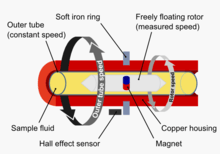
The outer cylinder of the Stabinger Viscometer is a tube that rotates at constant speed in a temperature-controlled copper housing. The hollow internal cylinder – shaped as a conical rotor – is specifically lighter than the filled samples and therefore floats freely within them, centered by centrifugal forces. In this way all bearing friction, an inevitable factor in most rotational devices, is fully avoided. The rotating fluid's shear forces drive the rotor, while a magnet inside the rotor forms an eddy current brake with the surrounding copper housing. An equilibrium rotor speed is established between driving and retarding forces, which is an unambiguous measure of the dynamic viscosity. The speed and torque measurement is implemented without direct contact by a Hall effect sensor counting the frequency of the rotating magnetic field. This allows for a highly precise torque resolution of 50 pN·m and a wide measuring range from 0.2 to 20,000 mPa•s with a single measuring system. A built-in density measurement based on the oscillating U-tube principle allows the determination of kinematic viscosity from the measured dynamic viscosity employing the relation

where:
- is the kinematic viscosity (mm2/s)
- is the dynamic viscosity (mPa.s)
- is the density (g/cm3)


Bubble viscometer
Bubble viscometers are used to quickly determine kinematic viscosity of known liquids such as resins and varnishes. The time required for an air bubble to rise is directly proportional to the viscosity of the liquid, so the faster the bubble rises, the lower the viscosity. The Alphabetical Comparison Method uses 4 sets of lettered reference tubes, A5 through Z10, of known viscosity to cover a viscosity range from 0.005 to 1,000 stokes. The Direct Time Method uses a single 3-line times tube for determining the "bubble seconds", which may then be converted to stokes.[6]
This method is considerably accurate, but the measurements can vary due to variances in buoyancy because of the changing in shape of the bubble in the tube [7] However, this does not cause any sort of serious miscalculation.
Rectangular-slit viscometer
The basic design of a rectangular-slit viscometer/rheometer, as commercially developed by RheoSense, Inc. of San Ramon, CA, consists of a rectangular, slit channel with uniform cross-sectional area. A test liquid is pumped at a constant flow rate through this channel. Multiple pressure sensors flush mounted at linear distances along the stream-wise direction measure pressure drop as depicted in Figure 1.
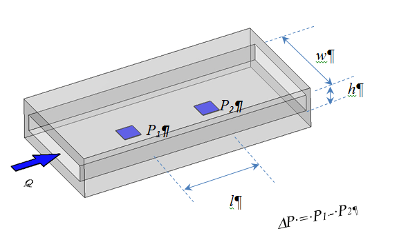
Measuring principle: The slit viscometer/rheometer is based on the fundamental principle that a viscous liquid resists flow, exhibiting a decreasing pressure along the length of the slit. The pressure decrease or drop (ΔP) is correlated with the shear stress at the wall boundary. The apparent shear rate is directly related to the flow rate and the dimension of the slit. The apparent shear rate, the shear stress, and the apparent viscosity are calculated:
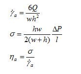
= Apparent Shear Rate (s−1)
σ = Shear Stress (Pa)
ηa = Apparent Viscosity (Pa-s)
ΔP = Pressure difference between the leading pressure sensor and the last pressure sensor (Pa)
Q = Flow Rate (ml/s)
w = width of the flow channel (mm)
h = depth of the flow channel (mm)
l = the distance between the leading pressure sensor and the last pressure sensor (mm)
To determine the viscosity of a liquid, pump the liquid sample to flow through the slit channel at a constant flow rate and measure the pressure drop. Following these equations, calculate the apparent viscosity for the apparent shear rate. For a Newtonian liquid, the apparent viscosity is the same as the true viscosity and the single shear rate measurement is sufficient. For non-Newtonian liquids, the apparent viscosity is not true viscosity. In order to obtain true viscosity, measure the apparent viscosities at multiple apparent shear rates. Then calculate true viscosities, η, at various shear rates using Weissenberg-Rabinowitsch-Mooney correction factor:

The calculated true viscosity will be the same as the cone and plate value at the same shear rate.
A modified version of the rectangular-slit viscometer/rheometer can also be used to determine apparent extensional viscosity.
Miscellaneous viscometer types
Other viscometer types use balls or other objects. Viscometers that can characterize non-Newtonian fluids are usually called rheometers or plastometers.
In the I.C.I "Oscar" viscometer, a sealed can of fluid was oscillated torsionally, and by clever measurement techniques it was possible to measure both viscosity and elasticity in the sample.
The Marsh funnel viscometer measures viscosity from the time (efflux time) it takes a known volume of liquid to flow from the base of a cone through a short tube. This is similar in principle to the flow cups (efflux cups) like the Ford, Zahn and Shell cups which use different shapes to the cone and various nozzle sizes. The measurements can be done according to ISO 2431, ASTM D1200 - 10 or DIN 53411.
The Flexible blade rheometer improves the accuracy of measurements for the lower viscosity range liquids utilizing the subtle changes in the flow field due to the flexibility of the moving or stationary blade (sometimes called wing or single side clamped cantilever).
See also
References
- ↑ "HAAKE - Falling Ball Viscometer C" (PDF).
- ↑ Grossi, Marco; Riccò, Bruno (2016). "A portable electronic system for in-situ measurements of oil concentration in MetalWorking fluids". Sensors and Actuators A: Physical. 243: 7–14. doi:10.1016/j.sna.2016.03.006.
- ↑ W. P. Mason, M. Hill: Measurement of the viscosity and shear elasticity of liquids by means of a torsionally vibrating crystal; Transactions of the ASME. In: Journal of Lubricating Technology. Band 69, 1947, S. 359–370.
- ↑ Berthold Bode: Entwicklung eines Quarzviskosimeters für Messungen bei hohen Drücken. Dissertation der TU Clausthal, 1984.
- ↑ http://flucon.de/produkte/quartz-viscosimeter-qvis/?lang=en<|accessdate=2015-07-02 |
- ↑ ASTM Paint and Coatings Manual 0-8031-2060-5
- ↑ ASTM Paint and Coatings Manual 0-8031-2060-5
- British Standards Institute BS ISO/TR 3666:1998 Viscosity of water
- British Standards Institute BS 188:1977 Methods for Determination of the viscosity of liquids
External links
- RHEOTEST Medingen GmbH - History and Collection of rheological instruments from the time of Fritz Höppler
- ASTM International (ASTM D7042)
- Viscosity conversion tables
- - Alpha Technologies (formerly Monsanto Instruments and Equipment) - Akron, Ohio USA
- Viscopedia | A free knowledge base for viscosity