Seismometer
| Part of a series on |
| Earthquakes |
|---|
| Types |
|
|
| Causes |
| Characteristics |
|
|
| Measurement |
| Prediction |
|
|
| Other topics |
|
Earth Sciences Portal Category • Related topics |
Seismometers are instruments that measure motion of the ground, including those of seismic waves generated by earthquakes, volcanic eruptions, and other seismic sources. Records of seismic waves allow seismologists to map the interior of the Earth, and locate and measure the size of these different sources.
The word derives from the Greek σεισμός, seismós, a shaking or quake, from the verb σείω, seíō, to shake; and μέτρον, métron, measure and was coined by David Milne-Home in 1841, to describe an instrument designed by Scottish physicist James David Forbes.[1]
Seismograph is another Greek term from seismós and γράφω, gráphō, to draw. It is often used to mean seismometer, though it is more applicable to the older instruments in which the measuring and recording of ground motion were combined than to modern systems, in which these functions are separated. Both types provide a continuous record of ground motion; this distinguishes them from seismoscopes, which merely indicate that motion has occurred, perhaps with some simple measure of how large it was.[2]
The concerning technical discipline is called seismometry,[3] a branch of seismology.
Basic principles
A simple seismometer that is sensitive to up-down motions of the earth can be understood by visualizing a weight hanging on a spring. The spring and weight are suspended from a frame that moves along with the earthʼs surface. As the earth moves, the relative motion between the weight and the earth provides a measure of the vertical ground motion. If a recording system is installed, such as a rotating drum attached to the frame, and a pen attached to the mass, this relative motion between the weight and earth can be recorded to produce a history of ground motion, called a seismogram.
Any movement of the ground moves the frame. The mass tends not to move because of its inertia, and by measuring the movement between the frame and the mass, the motion of the ground can be determined.
Early seismometers used optical levers or mechanical linkages to amplify the small motions involved, recording on soot-covered paper or photographic paper. Modern instruments use electronics. In some systems, the mass is held nearly motionless relative to the frame by an electronic negative feedback loop. The motion of the mass relative to the frame is measured, and the feedback loop applies a magnetic or electrostatic force to keep the mass nearly motionless. The voltage needed to produce this force is the output of the seismometer, which is recorded digitally. In other systems the weight is allowed to move, and its motion produces a voltage in a coil attached to the mass and moving through the magnetic field of a magnet attached to the frame. This design is often used in the geophones used in seismic surveys for oil and gas.
Professional seismic observatories usually have instruments measuring three axes: north-south (y-axis), east-west (x-axis), and the vertical (z-axis). If only one axis is measured, this is usually the vertical because it is less noisy and gives better records of some seismic waves.
The foundation of a seismic station is critical.[4] A professional station is sometimes mounted on bedrock. The best mountings may be in deep boreholes, which avoid thermal effects, ground noise and tilting from weather and tides. Other instruments are often mounted in insulated enclosures on small buried piers of unreinforced concrete. Reinforcing rods and aggregates would distort the pier as the temperature changes. A site is always surveyed for ground noise with a temporary installation before pouring the pier and laying conduit. Originally, European seismographs were placed in a particular area after a destructive earthquake. Today, they are spread to provide appropriate coverage (in the case of weak-motion seismology) or concentrated in high-risk regions (strong-motion seismology).[5]
History
Ancient era
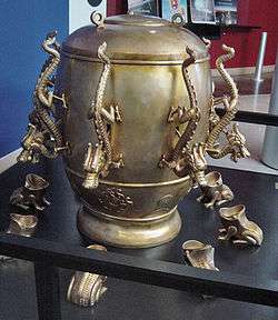
In AD 132, Zhang Heng of China's Han dynasty invented the first seismoscope (by the definition above), which was called Houfeng Didong Yi (translated as, "instrument for measuring the seasonal winds and the movements of the Earth"). The description we have, from the History of the Later Han Dynasty, says that it was a large bronze vessel, about 2 meters in diameter; at eight points around the top were dragon's heads holding bronze balls. When there was an earthquake, one of the mouths would open and drop its ball into a bronze toad at the base, making a sound and supposedly showing the direction of the earthquake. On at least one occasion, probably at the time of a large earthquake in Gansu in AD 143, the seismoscope indicated an earthquake even though one was not felt. The available text says that inside the vessel was a central column that could move along eight tracks; this is thought to refer to a pendulum, though it is not known exactly how this was linked to a mechanism that would open only one dragon's mouth. The first ever earthquake recorded by this seismoscope was supposedly somewhere in the east. Days later, a rider from the east reported this earthquake.[6][7]
Modern designs
The principle can be shown by an early special purpose seismometer. This consisted of a large stationary pendulum, with a stylus on the bottom. As the earth starts to move, the heavy mass of the pendulum has the inertia to stay still in the non-earth frame of reference. The result is that the stylus scratches a pattern corresponding with the Earth's movement. This type of strong motion seismometer recorded upon a smoked glass (glass with carbon soot). While not sensitive enough to detect distant earthquakes, this instrument could indicate the direction of the pressure waves and thus help find the epicenter of a local earthquake – such instruments were useful in the analysis of the 1906 San Francisco earthquake. Further re-analysis was performed in the 1980s using these early recordings, enabling a more precise determination of the initial fault break location in Marin county and its subsequent progression, mostly to the south.
After 1880, most seismometers were descended from those developed by the team of John Milne, James Alfred Ewing and Thomas Gray, who worked in Japan from 1880 to 1895.[5] These seismometers used damped horizontal pendulums. After World War II, these were adapted into the widely used Press-Ewing seismometer.
Later, professional suites of instruments for the worldwide standard seismographic network had one set of instruments tuned to oscillate at fifteen seconds, and the other at ninety seconds, each set measuring in three directions. Amateurs or observatories with limited means tuned their smaller, less sensitive instruments to ten seconds. The basic damped horizontal pendulum seismometer swings like the gate of a fence. A heavy weight is mounted on the point of a long (from 10 cm to several meters) triangle, hinged at its vertical edge. As the ground moves, the weight stays unmoving, swinging the "gate" on the hinge.
The advantage of a horizontal pendulum is that it achieves very low frequencies of oscillation in a compact instrument. The "gate" is slightly tilted, so the weight tends to slowly return to a central position. The pendulum is adjusted (before the damping is installed) to oscillate once per three seconds, or once per thirty seconds. The general-purpose instruments of small stations or amateurs usually oscillate once per ten seconds. A pan of oil is placed under the arm, and a small sheet of metal mounted on the underside of the arm drags in the oil to damp oscillations. The level of oil, position on the arm, and angle and size of sheet is adjusted until the damping is "critical," that is, almost having oscillation. The hinge is very low friction, often torsion wires, so the only friction is the internal friction of the wire. Small seismographs with low proof masses are placed in a vacuum to reduce disturbances from air currents.
Zollner described torsionally suspended horizontal pendulums as early as 1869, but developed them for gravimetry rather than seismometry.
Early seismometers had an arrangement of levers on jeweled bearings, to scratch smoked glass or paper. Later, mirrors reflected a light beam to a direct-recording plate or roll of photographic paper. Briefly, some designs returned to mechanical movements to save money. In mid-twentieth-century systems, the light was reflected to a pair of differential electronic photosensors called a photomultiplier. The voltage generated in the photomultiplier was used to drive galvanometers which had a small mirror mounted on the axis. The moving reflected light beam would strike the surface of the turning drum, which was covered with photo-sensitive paper. The expense of developing photo sensitive paper caused many seismic observatories to switch to ink or thermal-sensitive paper.
Modern instruments

Modern instruments use electronic sensors, amplifiers, and recording devices. Most are broadband covering a wide range of frequencies. Some seismometers can measure motions with frequencies from 500 Hz to 0.00118 Hz (1/500 = 0.002 seconds per cycle, to 1/0.00118 = 850 seconds per cycle). The mechanical suspension for horizontal instruments remains the garden-gate described above. Vertical instruments use some kind of constant-force suspension, such as the LaCoste suspension. The LaCoste suspension uses a zero-length spring to provide a long period (high sensitivity).[8][9] Some modern instruments use a "triaxial" design, in which three identical motion sensors are set at the same angle to the vertical but 120 degrees apart on the horizontal. Vertical and horizontal motions can be computed from the outputs of the three sensors.
Seismometers unavoidably introduce some distortion into the signals they measure, but professionally designed systems have carefully characterized frequency transforms.
Modern sensitivities come in three broad ranges: geophones, 50 to 750 V/m; local geologic seismographs, about 1,500 V/m; and teleseismographs, used for world survey, about 20,000 V/m. Instruments come in three main varieties: short period, long period and broadband. The short and long period measure velocity and are very sensitive, however they 'clip' the signal or go off-scale for ground motion that is strong enough to be felt by people. A 24-bit analog-to-digital conversion channel is commonplace. Practical devices are linear to roughly one part per million.
Delivered seismometers come with two styles of output: analog and digital. Analog seismographs require analog recording equipment, possibly including an analog-to-digital converter. The output of a digital seismograph can be simply input to a computer. It presents the data in a standard digital format (often "SE2" over Ethernet).
Teleseismometers
The modern broadband seismograph can record a very broad range of frequencies. It consists of a small "proof mass", confined by electrical forces, driven by sophisticated electronics. As the earth moves, the electronics attempt to hold the mass steady through a feedback circuit. The amount of force necessary to achieve this is then recorded.
In most designs the electronics holds a mass motionless relative to the frame. This device is called a "force balance accelerometer". It measures acceleration instead of velocity of ground movement. Basically, the distance between the mass and some part of the frame is measured very precisely, by a linear variable differential transformer. Some instruments use a linear variable differential capacitor.
That measurement is then amplified by electronic amplifiers attached to parts of an electronic negative feedback loop. One of the amplified currents from the negative feedback loop drives a coil very like a loudspeaker, except that the coil is attached to the mass, and the magnet is mounted on the frame. The result is that the mass stays nearly motionless.
Most instruments measure directly the ground motion using the distance sensor. The voltage generated in a sense coil on the mass by the magnet directly measures the instantaneous velocity of the ground. The current to the drive coil provides a sensitive, accurate measurement of the force between the mass and frame, thus measuring directly the ground's acceleration (using f=ma where f=force, m=mass, a=acceleration).
One of the continuing problems with sensitive vertical seismographs is the buoyancy of their masses. The uneven changes in pressure caused by wind blowing on an open window can easily change the density of the air in a room enough to cause a vertical seismograph to show spurious signals. Therefore, most professional seismographs are sealed in rigid gas-tight enclosures. For example, this is why a common Streckeisen model has a thick glass base that must be glued to its pier without bubbles in the glue.
It might seem logical to make the heavy magnet serve as a mass, but that subjects the seismograph to errors when the Earth's magnetic field moves. This is also why seismograph's moving parts are constructed from a material that interacts minimally with magnetic fields. A seismograph is also sensitive to changes in temperature so many instruments are constructed from low expansion materials such as nonmagnetic invar.
The hinges on a seismograph are usually patented, and by the time the patent has expired, the design has been improved. The most successful public domain designs use thin foil hinges in a clamp.
Another issue is that the transfer function of a seismograph must be accurately characterized, so that its frequency response is known. This is often the crucial difference between professional and amateur instruments. Most instruments are characterized on a variable frequency shaking table.
Strong-motion seismometers
Another type of seismometer is a digital strong-motion seismometer, or accelerograph. The data from such an instrument is essential to understand how an earthquake affects manmade structures.
A strong-motion seismometer measures acceleration. This can be mathematically integrated later to give velocity and position. Strong-motion seismometers are not as sensitive to ground motions as teleseismic instruments but they stay on scale during the strongest seismic shaking.
Other forms

Accelerographs and geophones are often heavy cylindrical magnets with a spring-mounted coil inside. As case moves, the coil tends to stay stationary, so the magnetic field cuts the wires, inducing current in the output wires. They receive frequencies from several hundred hertz down to 1 Hz. Some have electronic damping, a low-budget way to get some of the performance of the closed-loop wide-band geologic seismographs.
Strain-beam accelerometers constructed as integrated circuits are too insensitive for geologic seismographs (2002), but are widely used in geophones.
Some other sensitive designs measure the current generated by the flow of a non-corrosive ionic fluid through an electret sponge or a conductive fluid through a magnetic field.
Interconnected seismometers
Seismometers spaced in an array can also be used to precisely locate, in three dimensions, the source of an earthquake, using the time it takes for seismic waves to propagate away from the hypocenter, the initiating point of fault rupture (See also Earthquake location). Interconnected seismometers are also used to detect underground nuclear test explosions, as well as for Earthquake early warning systems. These seismometer are often used as part of a large scale governmental or scientific project, but some organizations such as the Quake-Catcher Network, can use residential size detectors built into computers to detect earthquakes as well.
In reflection seismology, an array of seismometers image sub-surface features. The data are reduced to images using algorithms similar to tomography. The data reduction methods resemble those of computer-aided tomographic medical imaging X-ray machines (CAT-scans), or imaging sonars.
A worldwide array of seismometers can actually image the interior of the Earth in wave-speed and transmissivity. This type of system uses events such as earthquakes, impact events or nuclear explosions as wave sources. The first efforts at this method used manual data reduction from paper seismograph charts. Modern digital seismograph records are better adapted to direct computer use. With inexpensive seismometer designs and internet access, amateurs and small institutions have even formed a "public seismograph network."[10]
Seismographic systems used for petroleum or other mineral exploration historically used an explosive and a wireline of geophones unrolled behind a truck. Now most short-range systems use "thumpers" that hit the ground, and some small commercial systems have such good digital signal processing that a few sledgehammer strikes provide enough signal for short-distance refractive surveys. Exotic cross or two-dimensional arrays of geophones are sometimes used to perform three-dimensional reflective imaging of subsurface features. Basic linear refractive geomapping software (once a black art) is available off-the-shelf, running on laptop computers, using strings as small as three geophones. Some systems now come in an 18" (0.5 m) plastic field case with a computer, display and printer in the cover.
Small seismic imaging systems are now sufficiently inexpensive to be used by civil engineers to survey foundation sites, locate bedrock, and find subsurface water.
Recording

Today, the most common recorder is a computer with an analog-to-digital converter, a disk drive and an internet connection; for amateurs, a PC with a sound card and associated software is adequate. Most systems record continuously, but some record only when a signal is detected, as shown by a short-term increase in the variation of the signal, compared to its long-term average (which can vary slowly because of changes in seismic noise).
Prior to the availability of digital processing of seismic data in the late 1970s, the records were done in a few different forms on different types of media. A "Helicorder" drum was a device used to record data into photographic paper or in the form of paper and ink. A "Develocorder" was a machine that record data from up to 20 channels into a 16-mm film. The recorded film can be viewed by a machine. The reading and measuring from these types of media can be done by hand. After the digital processing has been used, the archives of the seismic data were recorded in magnetic tapes. Due to the deterioration of older magnetic tape medias, large number of waveforms from the archives are not recoverable.[11][12]
See also
- Accelerometer
- Galitzine, Boris Borisovich
- Geophone
- Lehmann, Inge
- Milne, John
- Oldham, Richard Dixon
- Pacific Northwest Seismic Network
- Plate tectonics
- Quake-Catcher Network
- Richter Scale
- Seismogram
References
- ↑ Ben-Menahem, A. (2009). Historical Encyclopedia of Natural and Mathematical Sciences , Volume 1. Springer. p. 2657. ISBN 9783540688310. Retrieved 28 August 2012.
- ↑ Richter, C.F. (1958). Elementary Seismology. San Francisco: W.H. Freeman.
- ↑ William H.K. Lee; Paul Jennings; Carl Kisslinger; Hiroo Kanamori (27 September 2002). International Handbook of Earthquake & Engineering Seismology. Academic Press. pp. 283–. ISBN 978-0-08-048922-3. Retrieved 29 April 2013.
- ↑ Erhard Wielandt's 'Seismic Sensors and their Calibration'- Current (2002) reference by a widely consulted expert.
- 1 2 Reitherman, Robert (2012). Earthquakes and Engineers: an International History. Reston, VA: ASCE Press. pp. 122–125. ISBN 9780784410714.
- ↑ Sleeswyk AW, Sivin N (1983). "Dragons and toads: the Chinese seismoscope of BC. 132". Chinese Science. 6: 1–19.
- ↑ Needham, Joseph (1959). Science and Civilization in China, Volume 3: Mathematics and the Sciences of the Heavens and the Earth. Cambridge: Cambridge University Press. pp. 626–635.
- ↑ Zero Length Springs in Seismographs
- ↑ A Biography of Lucien LaCoste, inventor of the zero-length spring
- ↑ Public seismograph network- many resources for amateurs and underfunded institutions
- ↑ Hutton, Kate; Yu, Ellen. "NEWS FLASH!! SCSN Earthquake Catalog Completed!!" (PDF). Seismological Laboratory, Caltech. Retrieved 4 July 2014.
- ↑ Fogleman, Kent A.; Lahr, John C.; Stephens, Christopher D.; Page, Robert A. (June 1993). Earthquake Locations Determined by the Southern Alaska Seismograph Network for October 1971 through May 1989 (Report). USGS.
External links
| Wikimedia Commons has media related to Seismometers. |
- The history of early seismometers
- Link to live Seismic Drum at Geonet's Mangatainoka River station in New Zealand
- The Lehman amateur seismograph, from Scientific American- not designed for calibrated measurement.
- Sean Morrisey's professional design of an amateur teleseismograph Also see Keith Payea's version Both accessed 2010-9-29 Morrissey was a professional seismographic instrument engineer. This superior design uses a zero-length spring to achieve a 60-second period, active feedback and a uniquely convenient variable reluctance differential transducer, with parts scavenged from a hardware store. The frequency transform is carefully designed, unlike most amateur instruments. Morrisey is deceased, but the site remains up as a public service.
- USGS evaluation of Streckheisen STS-2 Seismometer models- Streckheisen is a common make of research seismometers
- Pacific Northwest Seismograph Network-PNSN is a seimograph network in the northwest USA
- SeisMac is a free tool for recent Macintosh laptop computers that implements a real-time three-axis seismograph.
- The Incorporated Research Institutions for Seismology (IRIS) is a principal U.S. seismological instrumentation and data facility, principally supported by the National Science Foundation and the U.S. Department of Energy.
- The Development Of Very-Broad-Band Seismography: Quanterra And The Iris Collaboration discusses the history of development of the primary technology in global earthquake research.
- Video of seismograph at Hawaiian Volcano Observatory - on Flickr - retrieved on 2009-06-15.
- Seismoscope - Research References 2012
- Iris EDU - How Does A Seismometer Work?