Artificial heart valve
An artificial heart valve is a device implanted in the heart of a patient with valvular heart disease.[1][2] When one of the four heart valves malfunctions, the medical choice may be to replace the natural valve with an artificial valve. This requires open-heart surgery.
Valves are integral to the normal physiological functioning of the human heart. Natural heart valves are evolved to forms that perform the functional requirement of inducing unidirectional blood flow through the valve structure from one chamber of the heart to another. Natural heart valves become dysfunctional for a variety of pathological causes. Some pathologies may require complete surgical replacement of the natural heart valve with a heart valve prosthesis.[3]
Types of heart valve prostheses
There are three main types of artificial heart valves: the mechanical,the biological, and the tissue engineered valves.
- Mechanical heart valve
- Percutaneous implantation
- Stent framed
- Not framed
- Sternotomy/Thoracotomy implantation
- Ball and cage
- Tilting disk
- Bi-leaflet
- Tri-leaflet
- Percutaneous implantation
- Tissue (biological) heart valves
- Tissue-Engineered heart valves
Mechanical valves
Mechanical heart valves (MHV) are prosthetics designed to replicate the function of the natural valves of the human heart. The human heart contains four valves: tricuspid valve, pulmonic valve, mitral valve and aortic valve. Their main purpose is to maintain unimpeded forward flow through the heart and from the heart into the major blood vessels connected to the heart, the pulmonary artery and the aorta. As a result of a number of disease processes, both acquired and congenital, any one of the four heart valves may malfunction and result in either stenosis (impeded forward flow) and/or backward flow (regurgitation). Either process burdens the heart and may lead to serious problems including heart failure. A mechanical heart valve is intended to replace a diseased heart valve with its prosthetic equivalent.
There are two basic types of valves that can be used for valve replacement, mechanical and tissue valves. Modern mechanical valves can last indefinitely (the equivalent of over 50,000 years in an accelerated valve wear tester). However, current mechanical heart valves all require lifelong treatment with anticoagulants (blood thinners), e.g. warfarin, which requires monthly blood tests to monitor. This process of thinning the blood is called anticoagulation. Tissue heart valves, in contrast, do not require the use of anticoagulant drugs due to the improved blood flow dynamics resulting in less red cell damage and hence less clot formation. Their main weakness however, is their limited lifespan. Traditional tissue valves, made of pig heart valves, will last on average 15 years before they require replacement (but typically less in younger patients).
Types of mechanical heart valves
2. Starr-Edwards Valve
3. Smeloff-Cutter Valve
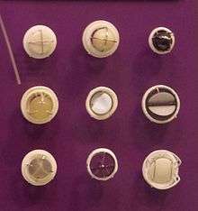
There are three major types of mechanical valves – caged-ball, tilting-disk and bileaflet valve – with many modifications on these designs.
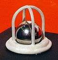
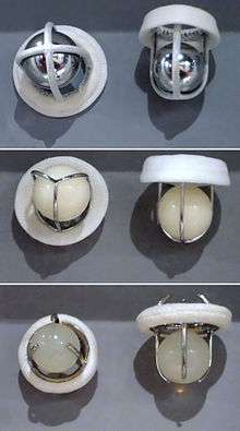
The first artificial heart valve was the caged-ball, which utilizes a metal cage to house a silicone elastomer ball. When blood pressure in the chamber of the heart exceeds that of the pressure on the outside of the chamber the ball is pushed against the cage and allows blood to flow. At the completion of the heart's contraction, the pressure inside the chamber drops and is lower than beyond the valve, so the ball moves back against the base of the valve forming a seal. In 1952, Charles A. Hufnagel implanted caged-ball heart valves in ten patients (six survived the operation), marking the first long-term success in prosthetic heart valves. A similar valve was invented by Miles "Lowell" Edwards and Albert Starr in 1960 (commonly referred to as the Starr-Edwards Silastic Ball Valve). The first human implant was on Sept 21, 1960. It consisted of a silicone ball enclosed in a cage formed by wires originating from the valve housing. Caged ball valves have a high tendency to forming blood clots, so the patient must have a high degree of anti-coagulation, usually with a target INR of 2.5-3.5. Edwards Lifesciences discontinued production of the Starr-Edwards valve in 2007.
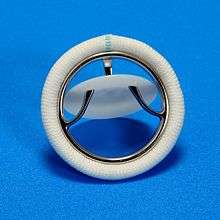
Soon after came tilting-disc valves. The first clinically available tilting disk valve was the Bjork-Shiley valve and has undergone several significant design changes since its introduction in 1969. Tilting disk valves have a single circular occluder controlled by a metal strut. They are made of a metal ring covered by an ePTFE fabric, into which the suture threads are stitched in order to hold the valve in place. The metal ring holds, by means of two metal supports, a disc which opens and closes as the heart pumps blood through the valve. The disc is usually made of an extremely hard carbon material (pyrolytic carbon), in order to allow the valve to function for years without wearing out. The Medtronic-Hall model is the most common tilting-disc design in the US. In some models of mechanical valves, the disc is divided into two parts, which open and close as a door.
Bileaflet heart valves consist of two semicircular leaflets that rotate about struts attached to the valve housing. This design was introduced in 1979 and while they take care of some of the issues that were seen in the other models, bileaflets are vulnerable to backflow and so they cannot be considered as ideal. Bileaflet valves do, however, provide much more natural blood flow than caged-ball or tilting-disc implants. One of the main advantages of these valves is that they are well tolerated by the body. Only a small amount of blood thinner is needed to be taken by the patient each day in order to prevent clotting of the blood when flowing through the valve.
These bileaflet valves have the advantage that they have a greater effective opening area (2.4–3.2 square cm c.f. 1.5–2.1 for the single-leaflet valves). Also, they are the least thrombogenic of the artificial valves.
Mechanical heart valves are today very reliable and allow the patient to live a normal life. Most mechanical valves last for at least 20 to 30 years.
Durability
Mechanical heart valves have been traditionally considered to be more durable in comparison to their bioprosthetic counterparts. The struts and occluders are made out of either pyrolytic carbon or titanium coated with pyrolytic carbon, and the sewing ring cuff is Teflon (PTFE), polyester or dacron. The major load arises from transvalvular pressure generated at and after valve closure, and in cases where structural failure does happen, it is usually as a result of occluder impact on the components.
Impact wear and friction wear dictate the loss of material in MHV. Impact wear usually occurs in the hinge regions of bileaflets, between the occluder and ring in tilting-discs, and between the ball and cage in caged-ball valves. Friction wear occurs between the occluder and strut in tilting-discs, and between the leaflet pivots and hinge cavities in bileaflets.
MHV, made out of metal are also susceptible to fatigue failure owing to the polycrystalline characteristic of metals, but this is not an issue with pyrolytic carbon MHV because this material is not crystalline in nature.
Cavitation
Cavitation is an event that can lead to MHV failure. While this has been a relatively rare occurrence, in 1988 the Edwards-Duramedics bileaflet had 46 reported failures in 20,000 implants related to cavitation damage. Since then, manufacturers have made cavitation testing an essential part of the design verification process. Cavitation is the rapid formation of vaporous microbubbles in the fluid due to a local drop of pressure below the vaporization pressure at a given temperature. When conditions for cavitation are present bubbles will form and at the time of pressure recovery they will collapse or implode. This event will cause pressure or thermal shockwaves and fluid microjets which can damage a surface. These thermodynamic conditions are known to be the cause of MHV related erosion.
The valvular event that causes such cavitating conditions to exist is the closing mechanics of the MHV. Several causes of cavitation relating to valve closure have been identified. Squeeze flow is cavitation that is said to occur as the occluder approaches the housing during closure and fluid is squeezed between the occluder and the valve housing causing a low pressure formation. Water hammer is cavitation caused by the sudden stop of the valve occluder as it contacts the valve housing. This sudden retardation of the fluid retrograde inertia is said to put the fluid under tension causing cavitation. Squeeze flow is said to form a cloud of bubbles at the circumferential lip of the occluder whereas water hammer is said to be seen as transient bubbles at the occlude housing.
For either event, cavitation occurs on the upstream side of valve. Clinically, cavitation is of primary concern in the mitral position. This position is especially harsh due to the sudden ventricular pressure rise which drives the valve closure against a low left atrial pressure which is said to be the worst case condition thus position for cavitation to occur. Cavitation is also suspected as a contributing factor in blood cell damage and increased risk of thromboembolic complications.
The temporal rate of change of the left ventricular, measured as a slope of the ventricular pressure curve (dP/dt) is regarded as the best indicator for cavitation potential. Most MHV investigated generate cavitation only when the dP/dt is well above the physiological range. However investigations have found that several tilting disc valves and only one bileaflet valve, the Edwards-Duromedics, generate cavitation within the physiological range. Investigations have repeatedly demonstrated that bileaflet valves, with the exception of the Edwards Duramedics design, cavitate only at dP/dt levels well above the physiological range.
Fluid mechanics
Many of the complications associated with MHV can be explained through fluid mechanics. For example, thrombus formation is a debilitating side effect of high shear stresses created by the design of the valves. An ideal heart valve from an engineering perspective would produce minimal pressure drops, have small regurgitation volumes, minimize turbulence, reduce prevalence of high stresses, and not create flow separations in the vicinity of the valve.
One measure of the quality of a valve is the effective orifice area (EOA), which can be calculated as follows:

where is the root mean square systolic/diastolic flow rate (cm³/s) and is the mean systolic/diastolic pressure drop (mmHg). This is a measure of how much the prosthesis impedes blood flow through the valve. A higher EOA corresponds to a smaller energy loss. The performance index (PI) normalizes the EOA by valve size and is a size-independent measure of the valve’s resistance characteristics. Bileaflet valves typically have higher PI’s than tilted-disc models, which in turn have higher PI’s than caged-ball models.


As blood flows through a prosthetic heart valve, a sudden pressure drop occurs across the valve due to the reduction in cross-sectional area within the valve housing. This can be quantified through the continuity equation and Bernoulli’s equation:


where A represents the cross-sectional area, P is pressure, is density, and V is the velocity. As cross-sectional area decreases in the valve, velocity increases and pressure drops as a result. This effect is more dramatic in caged-ball valves than in tilting-disc and bileaflet valves. A larger systolic pressure is required to drive flow forward in order to compensate for a large pressure drop, so it should be minimized.

Regurgitation is the sum of retrograde flow during the closing motion of the valve and leakage flow after closure. It is directly proportional to valve size and is also dependent on valve type. Typically, caged-ball valves have a low amount of regurgitation as there is very little leakage. Tilting-disc and bileaflet valves are comparable, with the bileaflet valves have a slightly larger regurgitation volume. Bioprosthetics prevail over MHV in this case, as they have virtually no regurgitation volume.
Turbulence and high shear stresses are also major issues with MHV, as they can fracture the valve housing or components, or induce blood damage. A large flow gradient can lead to these factors, so flow separation and stagnation should be as small as possible. High stresses are created at the edges of the annular jet in caged-ball valves, in narrow regions at the edges of the major orifice jet in tilting-disc valves, and in regions immediately distal to the valve leaflets in bileaflet valves. The implications of blood damage from these stresses are discussed in the next section.
The cavitation phenomenon can also be described using fluid mechanics. This can result from pressure oscillations, flow deceleration, tip vortices, streamline contraction, and squeeze jets. This last cause is the most contributive factor to cavitation. The squeeze jets are formed when the valve is closing and the blood between the occluder and valve housing is “squeezed” out to create a high-speed jet. This in turn creates intense vortices with very low pressures that can lead to cavitation.
Blood damage
One of the major drawbacks of mechanical heart valves is that patients with these implants require consistent anti-coagulation therapy. Clots formed by red blood cell (RBC) and platelet damage can block up blood vessels and lead to very serious consequences. Clotting occurs in one of three basic pathways: tissue factor exposure, platelet activation, or contact activation by foreign materials, and in three steps: initiation, amplification, and propagation.
In the tissue factor exposure path, initiation begins when cells are ruptured and expose tissue factor (TF). Plasma Factor (f) VII binds to TF and sets off a chain reaction which activates fXa and fVa which bind to each other to produce thrombin which in turn activates platelets and fVIII. The platelets activate by binding to the damaged tissue in the initiation phase, and fibrin stabilizes the clot during the propagation phase.
The platelet activation pathway is triggered when stresses reach a level above 6 to 8 Pa (60–80 dyn/cm²). The steps involved with this are less clearly understood, but initiation begins with the binding of vWF from the plasma to GPIb on the platelet. This is followed by a large influx of Ca2+ ions, which activates the platelets. GPIIb-IIIa facilitates platelet-platelet adhesion during amplification. The propagation step is still under study.
Contact activation begins when fXII binds to a procoagulant surface. This in turn activates prekallikrein (PK) and high-molecular-weight kininogen (HK). Eventually, HKa-PK and HKa-fXI complexes form on the surface. In amplification, Hka-FXIa complexes activate fIX to fIXa, which in turn forms thrombin and platelets. Proteins buildup on the surface and facilitate platelet adhesion and tissue growth in the propagation stage.
All MHV models are vulnerable to thrombus formation due to high shear stress, stagnation, and flow separation. The caged-ball designs experience high stresses at the walls that can damage cells, as well as flow separation due to high-velocity reverse flow surrounded by stagnant flow. Tilting-disc valves have flow separation behind the valve struts and disc as a result of a combination of high velocity and stagnant flows. The bileaflet models have high stresses during forward and leakage flows as well as adjacent stagnant flow in the hinge area. As it turns out, the hinge area is the most critical part of bileaflets and is where the thrombus formation usually prevails.
In general, blood damage affects valves in both the mitral and aortic positions. High stresses during leakage flow in aortal valves result from higher transvalvular pressures, and high stresses occur during forward flow for mitral valves. Valvular thrombosis is most common in mitral prosthetics. The caged-ball model is better than the other two models in terms of controlling this problem, because it is at a lower risk for thrombosis and it is gradual when it does happen. The bileaflet is more adaptable to this problem than the tilting-disc model because if one leaflet stops working, the other can still function. However, if the hinge is blocked, both leaflets will stop functioning.
Because all models experience high stresses, patients with mechanical heart valve implants require anti-coagulation therapy. Bioprosthetics are less prone to develop blood clotting, but the trade-off concerning durability generally favors their use in patients older than age 55.
Mechanical heart valves can also cause mechanical hemolytic anemia with hemolysis of the red blood cells as they pass through the valve.
Tissue (biological) valves
Biological valves are valves of animals, like pigs, which undergo several chemical procedures in order to make them suitable for implantation in the human heart. The porcine (or pig) heart is most similar to the human heart, and therefore represents the best anatomical fit for replacement. Implantation of a porcine valve is a type of xenotransplantation, also known as a xenograft, which means a transplant from one species (in this case a pig) to another. There are some risks associated with a xenograft such as the human body's tendency to reject foreign material. Medication can be used to retard this effect, but is not always successful.
Another type of biological valve utilizes biological tissue to make leaflets that are sewn into a metal frame. This tissue is typically harvested from the Pericardial Sac of either cows or horses. The pericardial sac is particularly well suited for a valve leaflet due to its extremely durable physical properties. This type of biological valve is extremely effective means of valve replacement. The tissue is sterilized so that the biological markers are removed, eliminating a response from the host's immune system. The leaflets are flexible and durable and do not require the patient to take blood thinners for the rest of their life.
The most used heart valves in the US,Britain and EU are those utilizing tissue leaflets. Mechanical valves are more commonly used in Asia and Latin America. The following companies manufacture tissue heart valves: Edwards Lifesciences, Medtronic, St. Jude Medical, Sorin, Medtronic ATS Medical, 3F Therapeutics, CryoLife, and LifeNet Health.
Recently, researchers have begun working to grow heart valves in vitro. Autologous cells are seeded on a scaffold, typically made from a biodegradable polymer such as PGA or PLA. The scaffolding acts as an artificial extra-cellular matrix, guiding tissue growth into the correct 3D structure of the heart valve. Mechanical stimuli must be simulated in the culture in order to condition the tissue for physiological stress in vivo. These heart valves have not yet reached clinical trials.[5]
Functional requirements of heart valve prostheses
The functioning of natural heart valves is characterized by many advantages:
- Minimal regurgitation – This means that the amount of blood lost upstream as the valve closes is small. For example, closure regurgitation through the mitral valve would result in some blood loss from the left ventricle to the left atrium as the mitral valve closes. Some degree of valvular regurgitation is inevitable and natural, up to around 5ml per beat.[6] However, several heart valve pathologies (e.g. rheumatic endocarditis) may lead to clinically significant valvular regurgitation. A desirable characteristic of heart valve prostheses is that regurgitation is minimal over the full range of physiological heart function (i.e. complete functional envelope of cardiac output vs. heart rate).
- Minimal transvalvular pressure gradient – Whenever a fluid flows through a restriction, such as a valve, a pressure gradient arises over the restriction. This pressure gradient is a result of the increased resistance to flow through the restriction. Natural heart valves have a low transvalvular pressure gradient as they present little obstruction to the flow through themselves, normally less than 16 mmHg. A desirable characteristic of heart valve prostheses is that their transvalvular pressure gradient is as small as possible.
- Non-thrombogenic – As natural heart valves are lined with an endothelium continuous with the endothelium lining the heart chambers they are not normally thrombogenic. This is important as should thrombi form on the heart valve leaflets and become seeded with bacteria, so called "bacterial vegetations" will form. Such vegetations are difficult for the body to deal with as the normal physiological defense mechanisms are not present within the valve leaflets because they are avascular and largely composed of connective tissue (Fixme: Create article discussing the pathgonesis of leaflet bacterial vegetations.). Should bacterial vegetations form on the valve leafets they may continually seed bacteria into the arterial tree which may lead to bacteremia or septicaemia. Portions of the vegetation may also break off forming septic emboli. Septic emboli can lodge anywhere in the arterial tree (e.g. brain, bowel, lungs) causing local infectious foci. Even dislodged fragments from uninfected thrombi can be hazardous as they can lodge in, and block, downstream arteries (e.g. coronary arteries leading to myocardial infarction, cerebral arteries leading to stroke, see embolism). A desirable characteristic of heart valve prostheses is that they are non or minimally thrombogenic.
- Self-repairing – Although of limited extent compared to well vascularised tissue (e.g. muscle), the valve leaflets do retain some capacity for repair due to the presence of regenerative cells (e.g. fibroblasts) in the connective tissue from which the leaflets are composed. As the human heart beats approximately 3.4x10⁹ times during a typical human lifespan this limited but nevertheless present repair capacity is critically important. No heart valve prostheses can currently self-repair but replacement tissues grown using stem cell technology may eventually offer such capabilities.
- Rapid dynamic response – STD
Design challenges of heart valve prostheses
- Thrombogenesis / haemocompatibility
- Mechanisms:
- Forward and backward flow shear
- Static leakage shear
- Presence of foreign material (i.e. intrinsic coagulation cascade)
- Cellular maceration
- Mechanisms:
- Valve-tissue interaction
- Wear
- Blockage
- Getting stuck
- Dynamic responsiveness
- Failure safety
- Valve orifice to anatomical orifice ratio
- Trans-valvular pressure gradient
- Minimal leakages
- Detachable And Replaceable Models Of Heart Valve Prostheses
Replaceable models of heart valve prostheses
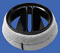
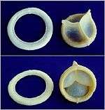
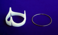
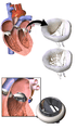
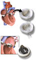
Mechanical or biological (bioprostheses or "tissue valves"), the replaceable models of implantable heart valve prostheses are made by two or three mechanical components. The gear attachment mechanism usually uses the coil effect or the bayonet coupling system.
The replaceable models of implantable heart valve prostheses are typically supplied with a sewing or suturing ring surrounding the valve body or stent that is to be sutured by the surgeon to the valvar rim.
The biggest challenge in this type of prostheses is the difficulty in its future removal. This is due to the formation of pannus fibrotic around the valve body and sewing ring. To separate the parts is very laborious, keeping intact the sewing ring, which will be used in the coupling of the new valve.
To easily remove the old replaceable bioprostheses, its "stent" can be sectioned to dismount its framework and so facilitate its removal from the sewing ring.
Time line of the detachable and replaceable models of heart valve prostheses:
- 1984 Martin, J. R [9]
- 1984 Martin, J. R [10]
- 1984 Martin, J. R [11]
- 1987 Fernandez J [12]
- 1988 Cooper DK [13]
- 1992 Lyra,R M [7]
- 1992 Lyra,R M [8]
- 1992 Jansen J [14]
Typical configuration of a heart valve prosthesis
- Anchor
- Leaflets
History
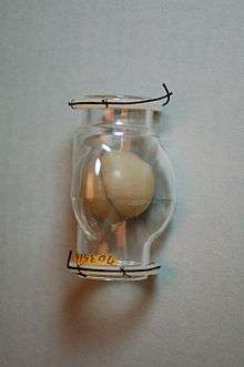
In the 1950s, Dr. Charles A. Hufnagel developed an artificial heart valve. His mechanical valve consisted of two parts, a ball that is surrounded by a cage which is the first variation of the ball-in-cage valves. Originally, the cage and the ball were constructed using Plexiglas. Due to the noise created by the contacts between the moving ball and the cage, the ball was later changed to use silicone-coated material.
The first implantation of mechanical heart valve to human was performed by Dr. Hufnagel on September 11, 1952 using the valve that he developed. This event accelerated the development of other artificial heart valves.[15]
Additional images
-
3D Rendering of Mechanical Valve
-
3D Rendering of Mechanical Valve (St. Francis model)
See also
References
- ↑ Bertazzo, Sergio; Gentleman, Eileen; Cloyd, Kristy L.; Chester, Adrian H.; Yacoub, Magdi H.; Stevens, Molly M. (2013). "Nano-analytical electron microscopy reveals fundamental insights into human cardiovascular tissue calcification". Nature Materials. 12 (6): 576–83. doi:10.1038/nmat3627. PMID 23603848.
- ↑ Miller, Jordan D. (2013). "Cardiovascular calcification: Orbicular origins". Nature Materials. 12 (6): 476–8. doi:10.1038/nmat3663. PMID 23695741.
- ↑ Pibarot, P.; Dumesnil, J. G. (2009). "Prosthetic Heart Valves: Selection of the Optimal Prosthesis and Long-Term Management". Circulation. 119 (7): 1034–48. doi:10.1161/CIRCULATIONAHA.108.778886. PMID 19237674.
- ↑ Kostrzewa, B; Rybak, Z (2013). "[History, present and future of biomaterials used for artificial heart valves].". Polimery w medycynie. 43 (3): 183–9. PMID 24377185.
- ↑ Neuenschwander, S., & P, H. S. (January 01, 2004). Heart valve tissue engineering. Transplant Immunology, 12, 359-365.
- ↑ Kasegawa, H; Iwasaki, K; Kusunose, S; Tatusta, R; Doi, T; Yasuda, H; Umezu, M (2012). "Assessment of a novel stentless mitral valve using a pulsatile mitral valve simulator". The Journal of heart valve disease. 21 (1): 71–5. PMID 22474745.
- 1 2 Lyra, R. M.; Leirner, A. A.; Pomerantzeff, Pablo Maria Alberto; Nyashida, S.; Jatene, Adib (1992). "Estudo in vitro, de uma bioprotese recambiavel" [In vitro study of a recambiavel bioprosthesis]. Revista da Sociedade de Cardiologia do Estado de São Paulo (in Portuguese). 2 (2 Suppl B): 71.
- 1 2 Lyra, R. M.; Leirner, A. A.; Pomerantzeff, Pablo Maria Alberto; Hyashida, S.; Jatene, Adib (1992). "Novo modelo de bioprotese recambiavel" [New model of recambiavel bioprosthesis]. Arquivos Brasileiros de Cardiologia. 59 (Suppl 2): 221.
- ↑ Martin, J. R; Grassi, E. D; Barone, A; Milei, J; Barone, H. D. (1984). "Protesis valvular cardiaca desmontable. Implante experimental 'in vivo' y resustitucion valvular alejada" [Dismountable heart valve prosthesis. In vivo experimental implant and delayed valvular replacement]. Revista Argentina de Cirugía (in Portuguese). 46 (6): 275–6.
- ↑ Martin, J. R; Barone, H. D; Barone, A; Milei, J; Grassi, E. D. (1984). "Anel portador de valvulas cardiacas" [Ring porter of cardiac valves] (PDF). Arquivos brasileiros de cardiologia (in Portuguese). 43 (6): 415–21. PMID 6399678.
- ↑ Martin, J. R; Grassi, E. D; Barone, A; Barone, H. D; Patane, A. M. (1984). "Protesis valvular cardiaca demontable Desarrollo experimental (Prototipo I)" [Dismountable heart valve prosthesis.Experimental development (Prototype I)]. Revista Argentina de Cirugía (in Portuguese). 46 (6): 272–4.
- ↑ Fernandez, J; Gonzalez-Lavin, L; Maranhao, V; Yang, SS (1987). "A new bioprosthesis for aortic and mitral valve replacement: Preliminary evaluation of the Tascon valve". Texas Heart Institute journal / from the Texas Heart Institute of St. Luke's Episcopal Hospital, Texas Children's Hospital. 14 (1): 31–8. PMC 324690
 . PMID 15227327.
 - ↑ Cooper, D.K.C.; Wicomb, W.N.; Gould, Gwyneth M.; Boonzaier, D. (1988). "Initial Experimental Experience with a 'Replaceable' Cardiac Valve Prosthesis". The Annals of Thoracic Surgery. 45 (5): 554–8. doi:10.1016/S0003-4975(10)64532-8. PMID 3365047.
- ↑ Jansen, Josef; Willeke, Sebastian; Reul, Helmul; Rau, Günter (2008). "Detachable Shape-Memory Sewing Ring for Heart Valves". Artificial Organs. 16 (3): 294–7. doi:10.1111/j.1525-1594.1992.tb00313.x. PMID 10078262.
- ↑ Butany, J; Ahluwalia, MS; Fayet, C; Munroe, C; Blit, P; Ahn, C (2002). "Hufnagel valve: the first prosthetic mechanical valve.". Cardiovascular Pathology. 11 (6): 351–3. PMID 12459437.
Further reading
- Bendet, IaA; Morozov, SM; Skumin, VA (1980). Психологические аспекты реабилитации больных после хирургического лечения пороков сердца [Psychological aspects of the rehabilitation of patients after the surgical treatment of heart defects]. Kardiologiia (in Russian). 20 (6): 45–51. PMID 7392405.
- Skumin, VA (1979). "Nurse's role in medico-psychological rehabilitation of patients with artificial heart valves". Meditsinskaia Sestra. 38 (9): 44–5. PMID 259874.
- Skumin, VA (1982). "Nonpsychotic mental disorders in patients with acquired heart defects before and after surgery (review)". Zhurnal nevropatologii i psikhiatrii imeni S.S. Korsakova. 82 (11): 130–5. PMID 6758444.
- Klepetko, W; Moritz, A; Mlczoch, J; Schurawitzki, H; Domanig, E; Wolner, E (1989). "Leaflet fracture in Edwards-Duromedics bileaflet valves". The Journal of Thoracic and Cardiovascular Surgery. 97 (1): 90–4. PMID 2911200.
- Podesser, BK; Khuenl-Brady, G; Eigenbauer, E; Roedler, S; Schmiedberger, A; Wolner, E; Moritz, A (1998). "Long-term results of heart valve replacement with the Edwards Duromedics bileaflet prosthesis: A prospective ten-year clinical follow-up". The Journal of Thoracic and Cardiovascular Surgery. 115 (5): 1121–9. doi:10.1016/s0022-5223(98)70412-x. PMID 9605082.
- Knapp RJ, Daily JW, Hammitt FG. 1970. Cavitation. New York: McGraw-Hill Int. Book Co.
- Lim, WL; Chew, YT; Low, HT; Foo, WL (2003). "Cavitation phenomena in mechanical heart valves: The role of squeeze flow velocity and contact area on cavitation initiation between two impinging rods". Journal of Biomechanics. 36 (9): 1269–80. doi:10.1016/s0021-9290(03)00161-1. PMID 12893035.
- Bluestein, D; Einav, S; Hwang, NH (1994). "A squeeze flow phenomenon at the closing of a bileaflet mechanical heart valve prosthesis". Journal of Biomechanics. 27 (11): 1369–78. doi:10.1016/0021-9290(94)90046-9. PMID 7798287.
- Graf, T; Fischer, H; Reul, H; Rau, G (1991). "Cavitation potential of mechanical heart valve prostheses". The International journal of Artificial Organs. 14 (3): 169–74. PMID 2045192.
- Kafesjian, R; Wieting, DW; Ely, J; Chahine, GL; Frederick, GS; Watson, RE (1990). "Characterization of Cavitation Potential of Pyrolitic Carbon". In Bodnar, Endré. Surgery for Heart Valve Disease: Proceedings of the 1989 Symposium. ICR. pp. 509–16. ISBN 978-1-872743-00-4.
- Chahine, GL (1996). "Scaling of mechanical heart valves for cavitation inception: Observation and acoustic detection". The Journal of Heart Valve Disease. 5 (2): 207–14; discussion 214–5. PMID 8665016.
- Zapanta, CM; Stinebring, DR; Sneckenberger, DS; Deutsch, S; Geselowitz, DB; Tarbell, JM; Synder, AJ; Rosenberg, G; Weiss, WJ; Pae, WE; Pierce, WS (1996). "In vivo observation of cavitation on prosthetic heart valves". ASAIO Journal. 42 (5): M550–5. doi:10.1097/00002480-199609000-00047. PMID 8944940.
- Richard, G; Beavan, A; Strzepa, P (1994). "Cavitation threshold ranking and erosion characteristics of bileaflet heart valve prostheses". The Journal of Heart Valve Disease. 3 Suppl 1: S94–101. PMID 8061875.
External links
- Page describing types of heart valve replacements
- "New Design for Mechanical Heart Valves". ScienceDaily. November 23, 2011.