Brayton cycle
| Thermodynamics | ||||||||||||
|---|---|---|---|---|---|---|---|---|---|---|---|---|
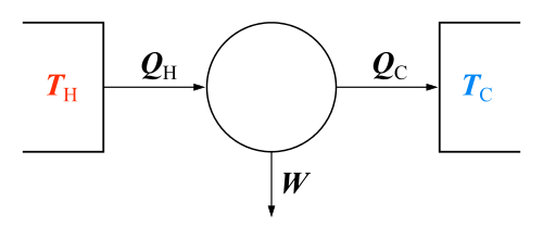 The classical Carnot heat engine | ||||||||||||
|
Branches |
||||||||||||
|
||||||||||||
| Book:Thermodynamics | ||||||||||||


The Brayton cycle is a thermodynamic cycle named after George Bailey Brayton that describes the workings of a constant pressure heat engine. The original Brayton engines used a piston compressor and piston expander, but more modern gas turbine engines and airbreathing jet engines also follow the Brayton cycle. Although the cycle is usually run as an open system (and indeed must be run as such if internal combustion is used), it is conventionally assumed for the purposes of thermodynamic analysis that the exhaust gases are reused in the intake, enabling analysis as a closed system.
The engine cycle is named after George Brayton (1830–1892), the American engineer who developed it originally for use in piston engines , although it was originally proposed and patented by Englishman John Barber in 1791.[1] It is also sometimes known as the Joule cycle. The Ericsson cycle is similar to the Brayton cycle but uses external heat and incorporates the use of a regenerator. There are two types of Brayton cycles, open to the atmosphere and using internal combustion chamber or closed and using a heat exchanger.
History

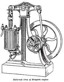

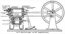
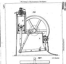
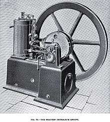
In 1872, George Brayton applied for a patent for his "Ready Motor," a reciprocating constant-pressure engine. The engine was a 2-stroke and produced power on every revolution. Brayton engines used a separate piston compressor and piston expander, with compressed air heated by internal fire as it entered the expander cylinder. The first versions of the Brayton engine were vapor engines which mixed fuel with air as it entered the compressor by means of a heated-surface carburetor.[2] The fuel / air was contained in a reservoir / tank and then it was admitted to the expansion cylinder and burned. As the fuel / air mixture entered the expansion cylinder it was ignited by a pilot flame. A screen was used to prevent the fire from entering / returning to the reservoir. In early versions of the engine, this screen sometimes failed and an explosion would occur. In 1874 Brayton solved the explosion problem by adding the fuel just prior to the expander cylinder. The engine now used heavier fuels such as kerosine and fuel oil. Ignition remained pilot flame.[3] Brayton produced and sold "Ready Motors" to perform a variety of tasks like water pumping, mill operation, running generators and marine propulsion. The "Ready Motors" were produced from 1872 to sometime in the 1880's. How many of these engines were produced is not known: probably there were several hundred; possibly a thousand. Brayton licensed the design to Simone in the UK. There were many variations of the layout; some were single-acting and some were double-acting. Some had under walking beams; others had overhead walking beams. There were both horizontal and vertical models. Sizes ranged from less than one horsepower to over 40 horsepower. Critics of the time claimed the engines ran smoothly and had a reasonable efficiency.[4]
Brayton cycle engines were some of the first internal combustion engines used for motive power. In 1875 John Holland used a Brayton engine to power the world's first self-propelled submarine (Holland boat #1). In 1879 a Brayton engine was used to power a second submarine, the Fenian Ram. John Philip Holland's submarines are preserved in the Paterson Museum in the Old Great Falls Historic District of Paterson, New Jersey.[5]
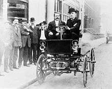
In 1878, George B. Selden patented the first internal combustion automobile.[6] Inspired by the internal combustion engine invented by George Brayton displayed at the Centennial Exposition in Philadelphia in 1876, Selden patented a 4 wheel car working on a smaller lighter multi-cylinder version. He then filed a series of amendments to his application which stretched out the legal process resulting in a delay of 16 years before the patent[7] was granted on November 5, 1895. In 1903 Selden sued Ford for patent infringement and Henry Ford fought the Selden patent until 1911. Selden had never actually produced a working car, so during the trial 2 machines were constructed according to the patent drawings. Ford argued his cars used the four-stroke Alphonse Beau de Rochas cycle or Otto cycle and not the Brayton cycle engine used in the Selden auto. Ford won the appeal of the original case.[8]
In 1887 Brayton developed and patented a 4 stroke direct injection oil engine (US patent #432,114 of 1890, application filed in 1887) The fuel system used a variable quantity pump and liquid fuel high pressure spray type injection. The liquid was forced through a spring loaded relief type valve (injector) which caused the fuel to become divided into small droplets. Injection was timed to occur at or near the peak of the compression stroke. A platinum igniter or ignitor provided the source of ignition. Brayton describes the invention as follows : “I have discovered that heavy oils can be mechanically converted into a finely-divided condition within a firing portion of the cylinder, or in a communicating firing chamber.” Another part reads “I have for the first time, so far as my knowledge extends, regulated speed by variably controlling the direct discharge of liquid fuel into the combustion chamber or cylinder into a finely-divided condition highly favorable to immediate combustion.” This was likely the first engine to use a lean-burn system to regulate engine speed / output. In this manner the engine fired on every power stroke and speed / output was controlled solely by the quantity of fuel injected.
In 1890 Brayton developed and patented a 4 stroke air blast oil engine (US patent #432,260) The fuel system delivered a variable quantity of vaporized fuel to the center of the cylinder under pressure at or near the peak of the compression stroke. The ignition source was an igniter made from platinum wire. A variable quantity injection pump provided the fuel to an injector where it was mixed with air as it entered the cylinder. A small crank driven compressor provided the source for air. This engine also used the lean burn system.
Diesel originally proposed a very high compression constant temperature cycle where the heat of compression would exceed the heat of combustion, however after several years of experiments it was realized that the constant temperature cycle would not work in a piston engine. Early Diesel engines use an air blast system which was pioneered by Brayton in 1890. Consequently these early engines use the constant pressure cycle. [9]
Just like steam turbines were adopted from steam piston engine so were gas turbines adopted from early piston constant pressure engines.
Early Gas Turbine History
1791 First patent for a gas turbine (John Barber, United Kingdom)
1904 Unsuccessful gas turbine project by Franz Stolze in Berlin (first axial compressor)
1906 GT by Armengaud Lemale in France (centrifugal compressor, no useful power)
1910 First GT featuring intermittent combustion (Holzwarth, 150 kW, constant volume combustion)
1923 First exhaust-gas turbocharger to increase the power of diesel engines
1939 World’s first gas turbine for power generation (Brown Boveri Company), Neuchâtel, Switzerland (velox burner, aerodynamics by Stodola)
Models
A Brayton-type engine consists of three components:
- a compressor
- a mixing chamber
- an expander
Modern Brayton engines are almost always a turbine type although Brayton only made piston engines. In the original 19th-century Brayton engine, ambient air is drawn into a piston compressor, where it is compressed; ideally an isentropic process. The compressed air then runs through a mixing chamber where fuel is added, an isobaric process. The pressurized air and fuel mixture is then ignited in an expansion cylinder and energy is released, causing the heated air and combustion products to expand through a piston/cylinder; another ideally isentropic process. Some of the work extracted by the piston/cylinder is used to drive the compressor through a crankshaft arrangement.
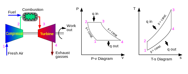
Gas turbines are also Brayton engines. This also has three components:
- a gas compressor
- a burner (or combustion chamber)
- an expansion turbine
Ideal Brayton cycle:
- isentropic process – ambient air is drawn into the compressor, where it is pressurized.
- isobaric process – the compressed air then runs through a combustion chamber, where fuel is burned, heating that air—a constant-pressure process, since the chamber is open to flow in and out.
- isentropic process – the heated, pressurized air then gives up its energy, expanding through a turbine (or series of turbines). Some of the work extracted by the turbine is used to drive the compressor.
- isobaric process – heat rejection (in the atmosphere).
Actual Brayton cycle:
- adiabatic process – compression
- isobaric process – heat addition
- adiabatic process – expansion
- isobaric process – heat rejection
 Idealized Brayton cycle |
Since neither the compression nor the expansion can be truly isentropic, losses through the compressor and the expander represent sources of inescapable working inefficiencies. In general, increasing the compression ratio is the most direct way to increase the overall power output of a Brayton system.[10]
The efficiency of the ideal Brayton cycle is , where is the heat capacity ratio.[11] Figure 1 indicates how the cycle efficiency changes with an increase in pressure ratio. Figure 2 indicates how the specific power output changes with an increase in the gas turbine inlet temperature for two different pressure ratio values.


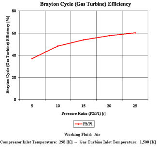

The highest temperature in the cycle occurs at the end of the combustion process, and it is limited by the maximum temperature that the turbine blades can withstand. This also limits the pressure ratios that can be used in the cycle. For a fixed turbine inlet temperature, the net work output per cycle increases with the pressure ratio (thus the thermal efficiency) and the net work output. With less work output per cycle, a larger mass flow rate (thus a larger system) is needed to maintain the same power output, which may not be economical. In most common designs, the pressure ratio of a gas turbine ranges from about 11 to 16.[12]
Methods to increase power
The power output of a Brayton engine can be improved in the following manners:
- Reheat, wherein the working fluid—in most cases air—expands through a series of turbines, then is passed through a second combustion chamber before expanding to ambient pressure through a final set of turbines. This has the advantage of increasing the power output possible for a given compression ratio without exceeding any metallurgical constraints (typically about 1000 °C). The use of an afterburner for jet aircraft engines can also be referred to as "reheat"; it is a different process in that the reheated air is expanded through a thrust nozzle rather than a turbine. The metallurgical constraints are somewhat alleviated, enabling much higher reheat temperatures (about 2000 °C). Reheat is most often used to improve the specific power (per throughput of air), and is usually associated with a drop in efficiency, this effect is especially pronounced in afterburners due to the extreme amounts of extra fuel used.
- Overspray, wherein, after a first compressor stage, water is injected into the compressor, thus increasing the mass-flow inside the compressor, increasing the turbine output power significantly and reducing compressor outlet temperatures.[13] In a second compressor stage the water is completely converted to a gas form, offering some intercooling via its latent heat of vaporization.
Methods to improve efficiency
The efficiency of a Brayton engine can be improved in the following manners:
- Increasing pressure ratio – As Figure 1 above shows, increasing the pressure ratio increases the efficiency of the Brayton cycle. This is analogous to the increase of efficiency seen in the Otto cycle when the compression ratio is increased. However, there are practical limits when it comes to increasing the pressure ratio. First of all, increasing the pressure ratio increases the compressor discharge temperature. This can cause the temperature of the gasses leaving the combustor to exceed the metallurgical limits of the turbine. Also, the diameter of the compressor blades becomes progressively smaller in higher pressure stages of the compressor. Because the gap between the blades and the engine casing increases in size as a percentage of the compressor blade height as the blades get smaller in diameter, a greater percentage of the compressed air can leak back past the blades in higher pressure stages. This causes a drop in compressor efficiency, and is most likely to occur in smaller gas turbines (since blades are inherently smaller to begin with). Finally, as can be seen in Figure 1, the efficiency levels off as pressure ratio increases. Hence, there is little to gain by increasing the pressure ratio further if it is already at a high level.
- Recuperator[14] – If the Brayton cycle is run at a low pressure ratio and a high temperature increase in the combustion chamber, the exhaust gas (after the last turbine stage) might still be hotter than the compressed inlet gas (after the last compression stage but before the combustor). In that case, a heat exchanger can be used to transfer thermal energy from the exhaust to the already compressed gas, before it enters the combustion chamber. The thermal energy transferred is effectively re-used, thus increasing efficiency. However, this form of heat recycling is only possible, if the engine is run in a low efficiency mode with low pressure ratio in the first place.
Note, that transferring heat from the outlet (after the last turbine) to the inlet (before the first compressor stage) would reduce efficiency, as hotter inlet air means more volume and thus more work for the compressor. For engines with liquid cryogenic fuels, namely Hydrogen, it might be feasible, though, to use the fuel to cool the inlet air before compression to increase efficiency. This concept is extensively studied for the SABRE engine. - A Brayton engine also forms half of the 'combined cycle' system, which combines with a Rankine engine to further increase overall efficiency. However, although this increases overall efficiency, it does not actually increase the efficiency of the Brayton cycle itself.
- Cogeneration systems make use of the waste heat from Brayton engines, typically for hot water production or space heating.
Variants
Closed Brayton cycle
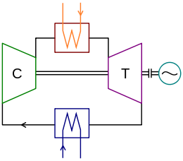
C compressor and T turbine assembly
w high-temperature heat exchanger
ʍ low-temperature heat exchanger
~ mechanical load, e.g. electric generator
A closed Brayton cycle recirculates the working fluid, the air expelled from the turbine is reintroduced into the compressor, this cycle uses a heat exchanger to heat the working fluid instead of an internal combustion chamber. The closed Brayton cycle is used for example in closed-cycle gas turbine and space power generation.
Solar Brayton cycle
In 2002, a hybrid open solar Brayton cycle was operated for the first time consistently and effectively with relevant papers published, in the frame of the EU SOLGATE program.[15] The air was heated from 570 K to over 1000 K into the combustor chamber. Further hybridization was achieved during the EU Solhyco project running a hybridized Brayton cycle with solar energy and Biodiesel only.[16] This technology was scaled up to 4.6 MW within the project Solugas located near Seville where it is currently demonstrated at pre-commercial scale.[17]
Reverse Brayton cycle
A Brayton cycle that is driven in reverse, via net work input, and when air is the working fluid, is the gas refrigeration cycle or Bell Coleman cycle. Its purpose is to move heat, rather than produce work. This air cooling technique is used widely in jet aircraft for air conditioning systems utilizing air tapped from the engine compressors. It is also used in the LNG industry where the largest reverse brayton cycle is for subcooling LNG using 86 MW of power from a gas turbine driven compressor and nitrogen refrigerant.[18]
See also
| Wikimedia Commons has media related to Brayton cycle. |
References
- ↑ according to Gas Turbine History Archived June 3, 2010, at the Wayback Machine.
- ↑ Frank A. Taylor (1939), "Catalog of the Mechanical Collections Of The Division Of Engineering", United States National Museum Bulletin 173, United States Government Printing Office, p. 147
- ↑ "IMPROVEMENT IN GAS-ENGINES (Patent no. 125166)". Google Patent Search. Retrieved 2007-07-29.
- ↑ "IMPROVEMENT IN GAS-ENGINES (Patent no. 125166)". Google Patent Search. Retrieved 2007-07-29.
- ↑ "Holland Submarines". Paterson Friends of the Great Falls. Archived from the original on 2007-08-12. Retrieved 2007-07-29.
- ↑ Original Selden patent
- ↑ US 549160 patent.pdf
- ↑ Link to Selden Patent information
- ↑ Early Diesel engines
- ↑ Lester C. Lichty, Combustion Engine Processes, 1967, McGraw-Hill, Inc., Library of Congress 67-10876
- ↑ http://web.mit.edu/16.unified/www/SPRING/propulsion/notes/node27.html Ideal cycle equations, MIT lecture notes
- ↑ Çengel, Yunus A., and Michael A. Boles. "9-8." Thermodynamics: An Engineering Approach. 7th ed. New York: McGraw-Hill, 2011. 508-09. Print.
- ↑ http://www.max-boost.co.uk/max-boost/resources/docs/SwirlFlash_WI.pdf
- ↑ "Brayton Thermodynamic Cycle".
- ↑ Research
- ↑ Solhyco.com Retrieved 2012-01-09
- ↑ Solugas.EU Retrieved 2014-11-09
- ↑ Largest LNG Compressors
External links
- Today in Science article on Brayton Engine
- http://scitation.aip.org/getabs/servlet/GetabsServlet?prog=normal&id=JSEEDO000126000003000872000001&idtype=cvips&gifs=yes
- http://elib.dlr.de/46328/
- Test and evaluation of a solar powered gas turbine system