Yagi–Uda antenna

A Yagi–Uda antenna, commonly known as a Yagi antenna, is a directional antenna consisting of multiple parallel elements in a line,[1] usually half-wave dipoles made of metal rods.[2] Yagi–Uda antennas consist of a single driven element connected to the transmitter or receiver with a transmission line, and additional parasitic elements: a so-called reflector and one or more directors.[2][3][4] It was invented in 1926 by Shintaro Uda of Tohoku Imperial University, Japan,[5] and (with a lesser role played by his colleague) Hidetsugu Yagi.[5][6]
The reflector element is slightly longer than the driven dipole, whereas the directors are a little shorter.[4] This design achieves a very substantial increase in the antenna's directionality and gain compared to a simple dipole.
Also called a "beam antenna",[4] or "parasitic array", the Yagi is very widely used as a high-gain antenna on the HF, VHF and UHF bands.[3][4] It has moderate to high gain which depends on the number of elements used, typically limited to about 20 dBi,[3] linear polarization,[3] unidirectional (end-fire) beam pattern[3] with high front-to-back ratio of up to 20 db. and is lightweight, inexpensive and simple to construct.[3] The bandwidth of a Yagi antenna, the frequency range over which it has high gain, is narrow, a few percent of the center frequency, and decreases with increasing gain,[3][4] so it is often used in fixed-frequency applications. The largest and best-known use is as rooftop terrestrial television antennas,[3] but it is also used for point-to-point fixed communication links,[2] in radar antennas,[4] and for long distance shortwave communication by shortwave broadcasting stations and radio amateurs.[2]
Origins
The antenna was invented in 1926 by Shintaro Uda of Tohoku Imperial University, Japan,[5] with a lesser role played by his colleague Hidetsugu Yagi.[6][7]
However the "Yagi" name has become more familiar with the name of Uda often omitted. This appears to have been due to Yagi filing a patent on the idea in Japan without Uda's name in it, and later transferring the patent to the Marconi Company in the UK.[8]
Yagi antennas were first widely used during World War II in radar systems by the British, US, Germans and Japanese.[7] After the war they saw extensive development as home television antennas.
Description

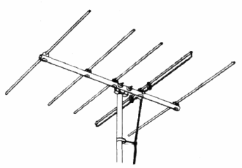
The Yagi–Uda antenna consists of a number of parallel thin rod elements in a line, usually half-wave long, typically supported on a perpendicular crossbar or "boom" along their centers.[2] There is a single driven element driven in the center (consisting of two rods each connected to one side of the transmission line), and a variable number of parasitic elements, a single reflector on one side and optionally one or more directors on the other side.[2][3][4] The parasitic elements are not electrically connected to the transmitter or receiver, and serve as passive radiators, reradiating the radio waves to modify the radiation pattern.[2] Typical spacings between elements vary from about 1/10 to 1/4 of a wavelength, depending on the specific design. The directors are slightly shorter than the driven element, while the reflector(s) are slightly longer.[4] The radiation pattern is unidirectional, with the main lobe along the axis perpendicular to the elements in the plane of the elements, off the end with the directors.[3]
Conveniently, the parasitic elements have a node (point of zero RF voltage) at their centre, so they can be attached to a conductive metal support at that point without need of insulation, without disturbing their electrical operation.[4] They are usually bolted or welded to the antenna's central support boom.[4] The driven element is fed at centre so its two halves must be insulated where the boom supports them.
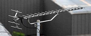
The gain increases with the number of parasitic elements used.[4] Only one reflector is used since the improvement of gain with additional reflectors is negligible, but Yagis have been built with up to 30–40 directors.[3]
The bandwidth of the antenna is the frequency range between the frequencies at which the gain drops 3 dB (one-half the power) below its maximum. The Yagi–Uda array in its basic form has very narrow bandwidth, 2–3 percent of the centre frequency.[4] There is a tradeoff between gain and bandwidth, with the bandwidth narrowing as more elements are used.[4] For applications that require wider bandwidths, such as terrestrial television, Yagi–Uda antennas commonly feature trigonal reflectors, traps (described below), and larger diameter conductors, in order to cover the relevant portions of the VHF and UHF bands.[9]
Yagi–Uda antennas used for amateur radio are sometimes designed to operate on multiple bands. These elaborate designs create electrical breaks along each element (both sides) at which point a parallel LC (inductor and capacitor) circuit is inserted. This so-called trap has the effect of truncating the element at the higher frequency band, making it approximately a half wavelength in length. At the lower frequency, the entire element (including the remaining inductance due to the trap) is close to half-wave resonance, implementing a different Yagi–Uda antenna. Using a second set of traps, a "triband" antenna can be resonant at three different bands. Given the associated costs of erecting an antenna and rotor system above a tower, the combination of antennas for three amateur bands in one unit is a very practical solution. The use of traps is not without disadvantages, however, as they reduce the bandwidth of the antenna on the individual bands and reduce the antenna's electrical efficiency and subject the antenna to additional mechanical considerations (wind loading, water and insect ingress).
Theory of operation
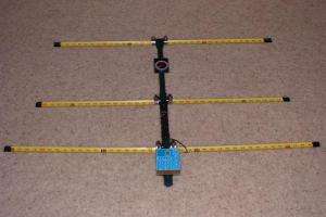
Consider a Yagi–Uda consisting of a reflector, driven element and a single director as shown here. The driven element is typically a λ/2 dipole or folded dipole and is the only member of the structure that is directly excited (electrically connected to the feedline). All the other elements are considered parasitic. That is, they reradiate power which they receive from the driven element (they also interact with each other).
One way of thinking about the operation of such an antenna is to consider a parasitic element to be a normal dipole element fed at its centre, with a short circuit across its feed point. As is well known in transmission line theory, a short circuit reflects all of the incident power 180 degrees out of phase. So one could as well model the operation of the parasitic element as the superposition of a dipole element receiving power and sending it down a transmission line to a matched load, and a transmitter sending the same amount of power up the transmission line back toward the antenna element. If the transmitted voltage wave were 180 degrees out of phase with the received wave at that point, the superposition of the two voltage waves would give zero voltage, equivalent to shorting out the dipole at the feedpoint (making it a solid element, as it is). Thus a half-wave parasitic element radiates a wave 180° out of phase with the incident wave.
The fact that the parasitic element involved is not exactly resonant but is somewhat shorter (or longer) than λ/2 modifies the phase of the element's current with respect to its excitation from the driven element. The so-called reflector element, being longer than λ/2, has an inductive reactance which means the phase of its current lags the phase of the open-circuit voltage that would be induced by the received field. The director element, on the other hand, being shorter than λ/2, has a capacitive reactance with the voltage phase lagging that of the current.[10]
The elements are given the correct lengths and spacings so that the radio waves radiated by the driven element and those reradiated by the parasitic elements all arrive at the front of the antenna in phase, so they superpose and add, increasing signal strength in the forward direction. In other words, the crest of the forward wave from the reflector element reaches the driven element just as the crest of the wave is emitted from that element. These waves reach the first director element just as the crest of the wave is emitted from that element, and so on. The waves in the reverse direction interfere destructively, cancelling out, so the signal strength radiated in the reverse direction is small. Thus the antenna radiates a unidirectional beam of radio waves from the front (director end) of the antenna.
Analysis
While the above qualitative explanation is useful for understanding how parasitic elements can enhance the driven elements' radiation in one direction at the expense of the other, the assumptions used are quite inaccurate. Since the so-called reflector, the longer parasitic element, has a current whose phase lags that of the driven element, one would expect the directivity to be in the direction of the reflector, opposite of the actual directional pattern of the Yagi–Uda antenna. In fact, that would be the case were we to construct a phased array with rather closely spaced elements all driven by voltages in phase, as we posited.
However these elements are not driven as such but receive their energy from the field created by the driven element, so we will find almost the opposite to be true. For now, consider that the parasitic element is also of length λ/2. Again looking at the parasitic element as a dipole which has been shorted at the feedpoint, we can see that if the parasitic element were to respond to the driven element with an open-circuit feedpoint voltage in phase with that applied to the driven element (which we'll assume for now) then the reflected wave from the short circuit would induce a current 180° out of phase with the current in the driven element. This would tend to cancel the radiation of the driven element. However, due to the reactance caused by the length difference, the phase lag of the current in the reflector, added to this 180° lag, results in a phase advance, and vice versa for the director. Thus the directivity of the array indeed is in the direction towards the director.
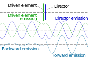

One must take into account an additional phase delay due to the finite distance between the elements which further delays the phase of the currents in both the directors and reflector(s). The case of a Yagi–Uda array using just a driven element and a director is illustrated in the accompanying diagram taking all of these effects into account. The wave generated by the driven element (green) propagates in both the forward and reverse directions (as well as other directions, not shown). The director receives that wave slightly delayed in time (amounting to a phase delay of about 35° which will be important for the reverse direction calculations later), and generating a current that would be out of phase with the driven element (thus an additional 180° phase shift), but which is further advanced in phase (by about 70°) due to the director's shorter length. In the forward direction the net effect is a wave emitted by the director (blue) which is about 110° (180°–70°) retarded with respect to that from the driven element (green), in this particular design. These waves combine to produce the net forward wave (bottom, right) with an amplitude slightly larger than the individual waves.
In the reverse direction, on the other hand, the additional delay of the wave from the director (blue) due to the spacing between the two elements (about 35° of phase delay traversed twice) causes it to be about 180° (110° + 2 × 35°) out of phase with the wave from the driven element (green). The net effect of these two waves, when added (bottom, left), is almost complete cancellation. The combination of the director's position and shorter length has thus obtained a unidirectional rather than the bidirectional response of the driven (half-wave dipole) element alone.
A full analysis of such a system requires computing the mutual impedances between the dipole elements[11] which implicitly takes into account the propagation delay due to the finite spacing between elements. We model element number j as having a feedpoint at the centre with a voltage Vj and a current Ij flowing into it. Just considering two such elements we can write the voltage at each feedpoint in terms of the currents using the mutual impedances Zij:


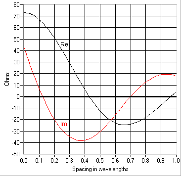
Z11 and Z22 are simply the ordinary driving point impedances of a dipole, thus 73 + j43 ohms for a half-wave element (or purely resistive for one slightly shorter, as is usually desired for the driven element). Due to the differences in the elements' lengths Z11 and Z22 have a substantially different reactive component. Due to reciprocity we know that Z21 = Z12. Now the difficult computation is in determining that mutual impedance Z21 which requires a numerical solution. This has been computed for two exact half-wave dipole elements at various spacings in the accompanying graph.
The solution of the system then is as follows. Let the driven element be designated 1 so that V1 and I1 are the voltage and current supplied by the transmitter. The parasitic element is designated 2, and since it is shorted at its "feedpoint" we can write that V2 = 0. Using the above relationships, then, we can solve for I2 in terms of I1:

and so
- .

This is the current induced in the parasitic element due to the current I1 in the driven element. We can also solve for the voltage V1 at the feedpoint of the driven element using the earlier equation:


where we have substituted Z12 = Z21. The ratio of voltage to current at this point is the driving point impedance Zdp of the 2-element Yagi:

With only the driven element present the driving point impedance would have simply been Z11, but has now been modified by the presence of the parasitic element. And now knowing the phase (and amplitude) of I2 in relation to I1 as computed above allows us to determine the radiation pattern (gain as a function of direction) due to the currents flowing in these two elements. Solution of such an antenna with more than two elements proceeds along the same lines, setting each Vj = 0 for all but the driven element, and solving for the currents in each element (and the voltage V1 at the feedpoint).[12]
Design

There are no simple formulas for designing Yagi–Uda antennas due to the complex relationships between physical parameters such as element length, spacing, and diameter, and performance characteristics such as gain and input impedance. But using the above sort of analysis one can calculate the performance given a set of parameters and adjust them to optimize the gain (perhaps subject to some constraints). Since with an N element Yagi–Uda antenna, there are 2N − 1 parameters to adjust (the element lengths and relative spacings), this is not a straightforward problem at all. The mutual impedances plotted above only apply to λ/2 length elements, so these might need to be recomputed to get good accuracy. What's more, the current distribution along a real antenna element is only approximately given by the usual assumption of a classical standing wave, requiring a solution of Hallen's integral equation taking into account the other conductors. Such a complete exact analysis considering all of the interactions mentioned is rather overwhelming, and approximations are inevitably invoked, as we have done in the above example.
Consequently, these antennas are often empirical designs using an element of trial and error, often starting with an existing design modified according to one's hunch. The result might be checked by direct measurement or by computer simulation. A well-known reference employed in the latter approach is a report published by the National Bureau of Standards (NBS) (now the National Institute of Standards and Technology (NIST)) that provides six basic designs derived from measurements conducted at 400 MHz and procedures for adapting these designs to other frequencies.[13] These designs, and those derived from them, are sometimes referred to as "NBS yagis."
By adjusting the distance between the adjacent directors it is possible to reduce the back lobe of the radiation pattern.
History
The Yagi–Uda antenna was invented in 1926 by Shintaro Uda of Tohoku Imperial University,[5] Sendai, Japan, with the collaboration of Hidetsugu Yagi, also of Tohoku Imperial University.[6] Yagi and Uda published their first report on the wave projector directional antenna. Yagi demonstrated a proof of concept, but the engineering problems proved to be more onerous than conventional systems.[14]
Yagi published the first English-language reference on the antenna in a 1928 survey article on short wave research in Japan and it came to be associated with his name. However, Yagi always acknowledged Uda's principal contribution to the design, and the proper name for the antenna is, as above, the Yagi–Uda antenna (or array).

The Yagi was first widely used during World War II for airborne radar sets, because of its simplicity and directionality.[14][15] Despite its being invented in Japan, many Japanese radar engineers were unaware of the design until very late in the war, partly due to rivalry between the Army and Navy. The Japanese military authorities first became aware of this technology after the Battle of Singapore when they captured the notes of a British radar technician that mentioned "yagi antenna". Japanese intelligence officers did not even recognise that Yagi was a Japanese name in this context. When questioned, the technician said it was an antenna named after a Japanese professor.[16][N 1]
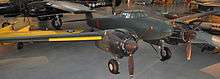
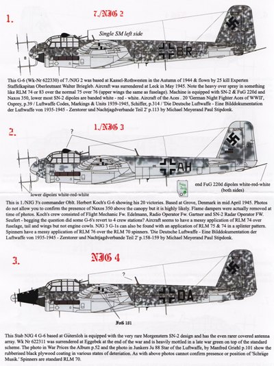
A horizontally polarized array can be seen under the leading edge of Grumman TBF Avenger carrier-based US Navy aircraft and the Consolidated PBY Catalina long range patrol seaplane. Vertically polarized arrays can be seen on the cheeks of the P-61 and on the nose cones of many WWII aircraft, notably the Lichtenstein radar-equipped examples of the German Junkers Ju 88R-1 fighter-bomber, and the British Bristol Beaufighter night-fighter and Short Sunderland flying-boat. Indeed, the latter had so many antenna elements arranged on its back – in addition to its formidable turreted defensive armament in the nose and tail, and atop the hull – it was nicknamed the fliegendes Stachelschwein, or "Flying Porcupine" by German airmen.[17] The experimental Morgenstern German AI VHF-band radar antenna of 1943–44 used a "double-Yagi" structure from its 90° angled pairs of Yagi antennas formed from six discrete dipole elements, making it possible to fair the array within a conical, rubber-covered plywood radome on an aircraft's nose, with the extreme tips of the Morgenstern's antenna elements protruding from the radome's surface, with an NJG 4 Ju 88G-6 of the wing's staff flight using it late in the war for its Lichtenstein SN-2 AI radar.[18]
After World War 2, the advent of television broadcasting motivated extensive development of the Yagi–Uda antenna as a rooftop television reception antenna in the VHF and UHF bands, and to a lesser extent an FM radio antenna. Until the development of the log periodic antenna in the 1960s it was the only type of antenna that could give adequate fringe reception in areas far from the television transmitter. A major drawback was the Yagi's inherently narrow bandwidth. Very complicated Yagi designs were developed to give adequate gain over the broad television bands. TV antennas are still a major application of the Yagi antenna.
The Yagi–Uda antenna was named an IEEE Milestone in 1995.[19]
See also
- Antenna (radio)
- Larmor formula
- Log-periodic dipole array
- Numerical Electromagnetics Code
- Radio direction finder
- Radio direction finding
Notes
- ↑ This story is analogous to the story of American intelligence officers interrogating German rocket scientists and finding out that Robert Goddard was the real pioneer of rocket technology even though he was not well known in the US at that time.
References
- Citations
- ↑ Graf, Rudolf F. (1999). Modern Dictionary of Electronics (7 ed.). Newnes. p. 858. ISBN 0080511988.
- 1 2 3 4 5 6 7 "What Is a Yagi Antenna?". wiseGEEK website. Conjecture Corp. 2014. Retrieved 18 September 2014.
- 1 2 3 4 5 6 7 8 9 10 11 Balanis, Constantine A. (2011). Modern Antenna Handbook. John Wiley and Sons. pp. 2.17–2.18. ISBN 1118209753.
- 1 2 3 4 5 6 7 8 9 10 11 12 13 Wolff, Christian (2010). "Yagi Antenna". Radar Basics. Radartutorial.eu. Retrieved 18 September 2014.
- 1 2 3 4 Uda, S. (December 1925). "On the Wireless Beam of Short Electric Waves". Jour. of IEE of Japan. Institute of Electrical Engineers of Japan: 1128. (This was the preface and notice in advance for a series of 11 papers with the same title by Uda between 1926–1929 on the antenna.)
- 1 2 3 Yagi, Hidetsu; Uda, Shintaro (February 1926). "Projector of the Sharpest Beam of Electric Waves" (PDF). Proc. of the Imperial Academy of Japan. Imperial Academy. 2 (2): 49–52. Retrieved 11 September 2014.
- 1 2 Sarkar, T. K.; Mailloux, Robert; Oliner, Arthur A.; et al. (2006). History of Wireless. John Wiley and Sons. pp. 462–466. ISBN 0471783013.
- ↑ "Y. Mushiake, '"Notes on the History of Yagi-Uda Antenna."' IEEE Antennas and Propagation Magazine, Vol. 56, No. 1, February 2014. pp. 255-257.". Sm.rim.or.jp. Retrieved 4 July 2014.
- ↑ Common TV Antenna Types
- ↑ Pozar (2001)
- ↑ Principles of Antenna Theory, Kai Fong Lee, 1984, John Wiley and Sons Ltd., ISBN 0-471-90167-9
- ↑ S. Uda; Y. Mushiake (1954). Yagi-Uda Antenna. Sendai, Japan: The Research Institute of Electrical Communication, Tohoku University.
- ↑ Yagi Antenna Design, Peter P. Viezbicke, National Bureau of Standard Technical Note 688, December 1976
- 1 2 Brown, 1999, p. 138
- ↑ Graf, Rudolf F. (June 1959). "Make Your Own UHF Yagi Antenna". Popular Mechanics, pp. 144–145, 214.
- ↑ 2001 IEEE Antennas and Propagation Society International Symposium By IEEE Antennas and Propagation Society. International Symposium.
- ↑ The Sunderland flying-boat queen, Volume 1 By John Evans, Page 5
- ↑ "HyperScale 48D001 Ju 88 G-6 and Mistel S-3C Collection decals". Hyperscale.com. Retrieved 15 April 2012.
- ↑ "Milestones:Directive Short Wave Antenna, 1924". IEEE Global History Network. IEEE. Retrieved 29 July 2011.
- Bibliography
- Brown, Louis (1999). A radar history of World War II: technical and military imperatives. CRC Press. ISBN 0-7503-0659-9
- S. Uda, "High angle radiation of short electric waves". Proceedings of the IRE, vol. 15, pp. 377–385, May 1927.
- S. Uda, "Radiotelegraphy and radiotelephony on half-meter waves". Proceedings of the IRE, vol. 18, pp. 1047–1063, June 1930.
- J. E. Brittain, Scanning the Past, Shintaro Uda and the Wave Projector, Proc. IEEE, May 1997, pp. 800–801.
- H .Yagi, Beam transmission of ultra-shortwaves, Proceedings of the IRE, vol. 16, pp. 715–740, June 1928. The URL is to a 1997 IEEE reprint of the classic article. See also Beam Transmission Of Ultra Short Waves: An Introduction To The Classic Paper By H. Yagi by D.M. Pozar, in Proceedings of the IEEE, Volume 85, Issue 11, Nov. 1997 Page(s):1857–1863.
- "Scanning the Past: A History of Electrical Engineering from the Past". Proceedings of the IEEE Vol. 81, No. 6, 1993.
- Shozo Usami and Gentei Sato, "Directive Short Wave Antenna, 1924". IEEE Milestones, IEEE History Center, IEEE, 2005.
- Pozar, David M. (2001). Microwave and RF Design of Wireless Systems. John Wiley & Sons Inc. p. 134. ISBN 978-0-471-32282-5.
External links
| Wikimedia Commons has media related to Yagi-Uda antennas. |
- Yagi-Uda antenna History". History of antenna invention and its patents.
- D. Jefferies, "Yagi-Uda antennas". 2004.
- Yagi-Uda Antenna. Simple information on basic design, project and measure of Yagi–Uda antenna. 2008
- Yagi-Uda Antennas www.antenna-theory.com